Vertiv™ XTE 802G Generator Room Walk-In-Cabinet Description and Installation Manual
27
12.
Install the four corner plates on the leveling hardware, one in each corner. See
Figure 6-4:
Install Four Corner Plates
13.
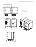
Level and secure all the leveling hardware on the corner plates and helicals, paying attention to 68.85 inch centers. The
leveling hardware should not be installed outside the 3 inch radius of the helical pipe. The corner plates have elongated
holes for 2 inches of play. There is a lot of room for adjustments to accomplish the 68.85 inch centers. See
Figure 6-5:
Helicals and Corner Plates
14.
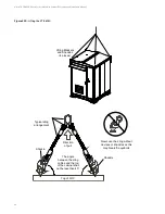
Lift and set XTE 802G on Helical Foundation Kit. Be sure to bolt the XTE 802G base to the corner plates prior to releasing all
of the weight of the XTE 802G on the corner plates. See “XTE 802G Lifting and Placement Procedures” starting on page 39.
15.
Once all hardware is installed connecting the XTE 802G base to all corner plates, tighten and secure all the hardware.
16.
Install the stairs using the provided hardware.
The helical foundation is designed to minimize soil disturbance and time involved for installation compared to other types of
foundations. The minimum requirements for properly installed helical pier are 1) to achieve penetration so the pier’s top base plate is
11 inches above grade and 2) achieve a minimum torque value of 3,000 foot-pounds. A maximum torque value of 15,000 foot-pounds
should be used. In the event the helical foundation cannot be installed per the standard procedure above, one of the following
Alternative Procedures should be used.

