Vertiv™ NetSure™ A50B50 DC Power Retrofit Installation and User Instructions
``
15
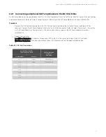
Table 3.5
Switch S1 Settings
Resistance Values of Group (See
Table 5)
Switch S1 Settings
Settings Capable with Alarm and Control Panel(s), Part
No(s).
Switch Position
Open/ Close
1
1
Open
437422100
437422800
437423000
437423100
2
Open
3
Open
4
Closed
2
1
Open
437420600, 437420700,
437420800, 437420900,
437421600, 437421900,
437422300, 437423300,
437423400
2
Open
3
Closed
4
Open
3
1
Open
437417400
2
Closed
3
Open
4
Open
Ground (+BAT)
Signal Provided
1
Closed
--
2
Open
3
Open
4
Open
Table 3.6
Three Groups of Resistance Values
No. of Failed
Modules
Alarm Resistance Value
(Ohms)
Group 1
Alarm Resistance Value
(Ohms)
Group 2
Alarm Resistance Value
(Ohms)
Group 3
1
27.4K
41.2K
10K
2 or more
7.3K
8K
5K
3.2.2
Installing the Controller
Procedure
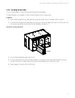
Refer to the following and place the NCU controller into the controller mounting position.
ALERT!
CONTROLLER HANDLING.
Installation or removal of the controller requires careful handling. To avoid possibility of controller damage from static
discharge, a static wrist strap grounded through a one megohm resistor should always be worn when handling the controller.
ESD protective packaging material must also be used when carrying/shipping the controller.
NOTE!
Depending on your network security settings, when you remove a device that is connected to your network and
assign the same IP address to the replacement device, you may not be allowed to communicate with the replacement device
over the network. Contact your network administrator for assistance.
NOTE!
The controller is hot swappable. It can be removed and installed with the system operating and without affecting the
output bus.


