Vertiv™ NetSure™ A50B50 DC Power Retrofit Installation and User Instructions
``
3
3.2
Electrical Connections
Wiring Considerations
The AC input, DC output, and system alarm connections on the frame mate with the existing connectors in the shelf. No adjustments
or alterations are required for these connections.
Making CAN Connections
CAN connections are made to allow expansion frames (A50EFRM) to connect to the main frame (A50IFRM) for rectifier control and
alarming. Follow the procedure below.
NOTE!
If only one frame (A50IFRM) is used for application, install the furnished CAN bus termination plug (P/N 547678) to
terminate the bus. This terminator is inserted into the socket at the upper right side of the frame. Refer to Figure 3.3 for
details.
Single Shelf
1.
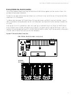
To connect adjacent frames in one existing shelf, use the 6-in long P/N 548451 CAN cable for each connection. Refer to
Figure 3.3 for a sample configuration of (1) A50IFRM and (2) A50EFRMs.
Figure 3.3
CAN Connections in a Single Shelf
2.
To terminate the bus, plug the furnished termination plug (P/N 547678) into the right-hand CAN port of the last frame.
P/N 547678
Terminator
P/N 548451
6” CAN cable
Single Shelf CAN Connection
A50IFRM
A50EFRM
A50EFRM
A50IFRM
A50EFRM
A50EFRM
DETAILS
SM-Temp
Module
or
(RJ-45)


