Vertiv™ NetSure™ A50B50 DC Power Retrofit Installation and User Instructions
6
Making IB2 Board Connections
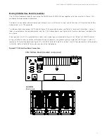
Digital inputs, relay outputs, and temperature probe(s) are connected to the IB2 Board. Refer to Figure 3.5 for connector locations,
and Table 3.1 and Table 3.2 for pin-out information.
If required to access these connection points, loosen the captive fastener on the front of the IB2 Board, and slide the assembly
partially out of the shelf. Recommended torque for the Digital Input and Relay Output terminal blocks is 5 in-lbs.
Connecting Digital Inputs
Connect up to six (6) digital inputs to the IB2 Board. (Inputs 7 and 8 are factory connected, as listed in Table 3.1.)
All user-defined digital inputs are set to alarm on a HIGH signal. Refer to the controller’s User Manual for instructions on how to set
these signals to be active LOW if desired.
An active HIGH signal means a voltage must be applied to generate an alarm. For example, if Digital Input No. 1 is used, connect -48V
RTN to (+) and -48V to (-) to generate an alarm.
An active LOW signal means no voltage will generate an alarm. For example, if Digital Input No. 1 is used, connect -48V RTN to (+)
and -48V to (-) for no alarm. Removing any of the signals will then generate an alarm.
The digital inputs can be configured to provide an alarm when the signal is applied (HIGH) or removed (LOW).
Connecting Relay Outputs
The IB2 Board provides five (5) programmable alarm relays with Form-C contacts. Refer to Table 3.2 for pin-out information. (Relays 6
through 8 are factory connected, as listed in Table 3.2.)
Refer to the notes in Figure 3.5 for relay operation.


