8
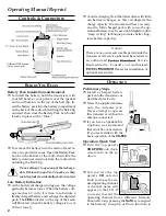
One or more of the radio’s "Soft Keys" may be en-
abled for a function associated with the "Set" (Menu)
mode. This feature, when activated, allows the user
to customize certain performance aspects of the VX-
800. Note that some of these items may also appear
as available "Soft Keys," described below.
The operating procedure for the Menu mode is quite
simple, requiring only a few easily- remembered
actions on the user’s part.
The VX-800 Soft Keys include the [
SEL1
], [
SEL2
],
[
MON
], and [
LAMP
] Keys, plus the [
A
], [
B
], [
C
], and
[
D
] keys on the 16-key version. The Soft Key func-
tions can be assigned either as a "Menu" function or
an "operating" function at the time of programming.
Basic Menu Mode Operation
1. Press the appropriate Soft Key to activate a Menu
function. The available keys include the [
SEL1
],
[
SEL2
], [
MON
], and [
LAMP
] Keys, plus the [
A
],
[
B
], [
C
], and [
D
] keys on the 16-key version.
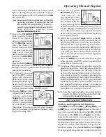
2. Rotate the top panel’s
CH
selector knob to select
the feature you wish to view and/or modify.
3. Press the [
SEL1
] and/or [
SEL2
] keys to modify or
adjust the current setting of this Menu item ("On"
to "Off," etc.)
4. Rotate the
CH
selector to save the new setting.
5. Press the
PTT
switch to exit the Set (Menu) mode.
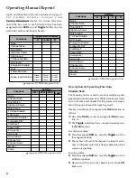
Available Soft Key Menu Functions
No.1 SQL (Squelch Level)
After selecting this Menu, press the [
SEL1
] or
[
SEL2
] key to find the point where the background
noise is just silenced. This is the point of best re-
ceiver sensitivity consistent with quiet monitoring.
The scale for the Squelch Level adjustment is 0 ~ 11
and 12 (RSSI SQL), The default value is 8.
When the Squelch Level set to "12" activates the RSSI
(Received Signal Strength Indicator) Squelch feature,
which allows you to set the squelch so that only sig-
nals exceeding a prescribed RX signal input level
will open the squelch. The RX signal input level is
determined via the Alignment Program SVC31. See
page 20 for details regarding the RSSI level setting.
No.2 LIST (Scanning List)
The VX-800 has two scanning "list:" the "Dealer Scan"
list and the "User Scan" list. The "Dealer scan" list is
a fixed group of stations which will be included
when scanning is activated. The "User Scan" list is a
different list, initially arranged by the dealer, by the
User.
This Menu Item allows you to select the scanning
list "Dealer Scan" or "User Scan".
After selecting this Menu, press the [
SEL1
] or [
SEL2
]
key to select the Scan List in which you wish to scan
("LIST DLR: Dealer List" or "LIST USR: User List").
Rotate the CH selector knob to save the new setting,
then press the PTT switch to exit the Set (Menu)
mode.
No.3 BEEP (Keypad Beeper On/Off)
After selecting this Menu, press the [
SEL1
] or [
SEL2
]
key to enable (ON) or disable (OFF) the keypad beep
tones. Rotate the
CH
selector knob to save the new
setting, then press the
PTT
switch to exit the Set
(Menu) mode.
No.4 BELL (CTCSS/DCS/Paging Alert Bell On/Off)
After selecting this Menu, press the [
SEL1
] or [
SEL2
]
key to enable (ON) or disable (OFF) the alert bell
which sounds when your radio is called using ei-
ther CTCSS or DCS calling tones. Rotate the
CH
se-
lector knob to save the new setting, then press the
PTT
switch to exit the Set (Menu) mode.
No.5 LGT (TX/BUSY LED On/Off)
After selecting this Menu, press the [
SEL1
] or [
SEL2
]
key to enable (ON) or disable (OFF) the LED which
serves as the Busy Channel and Transmitter On in-
dicator. Turning this LED off will extend battery life
somewhat. Rotate the
CH
selector knob to save the
new setting, then press the
PTT
switch to exit the
Set (Menu) mode.
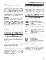
No.6 LOCK (Keypad, PTT, or Knob Disabling)
In some situations, you may wish to disable the key-
pad's keys, the
CH
selector knob, and/or the
PTT
switch (so as to prevent transmission by unautho-
rized users of the radio). LOCK Menu determines
which features will be disabled when the LOCK
function is engaged.
Set (Menu) Mode Functions
Содержание VX-800
Страница 10: ...10 Set Menu Mode Functions Note ...
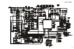
Страница 13: ...13 Block Diagram ...
Страница 14: ...14 Note Block Diagram ...
Страница 24: ...24 Note ...
Страница 26: ...26 Main Unit Lot 1 3 Note ...
Страница 29: ...29 Main Unit Lot 4 50 Circuit Diagram ...
Страница 30: ...30 Main Unit Lot 4 50 Note ...
Страница 33: ...33 Main Unit Lot 51 Circuit Diagram ...
Страница 34: ...34 Main Unit Lot 51 Note ...


