23
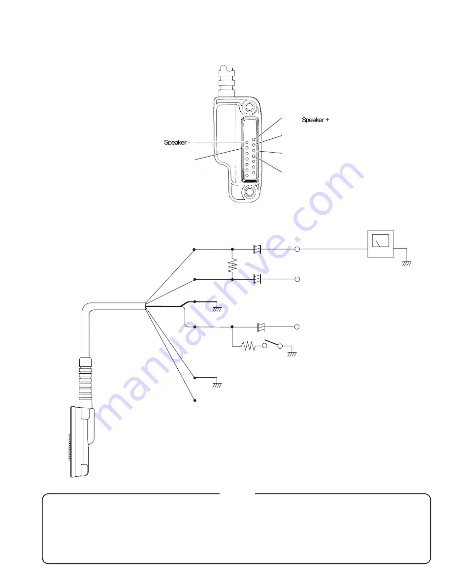
Test Adapter Schematic
Connector Pinout Diagram
AF Test Adapter Schematic
Note!
Because of the bridge audio amplifier circuit used in the VX-800, it is necessry to construct and use
a simple audio load test adapter as shown in the schematic diagram above, when conducting
receiver alignment steps.
Do not connect either side of the speaker leads to chassis "ground."
Pin 2 (
)
Pin 4 (MIC)
Pin 1 (
)
Pin 3 (GND)
Pin 5 (Select)
Pin 7 (Clone)
YAESU P/N: T9206933
White (Pin 1: S)
Blue (Pin 2: Speaker -)
Red (Pin 4: MIC)
Green (Pin 5: Select)
N.C. Yellow (Pin 7: Clone)
Shield (Pin 3: GND)
16-ohm
2w
220µF
+
+
220µF
+
1µF
2.2K-ohm
PTT
AF Output
Audio Generator
Attenuated
Test Output (1/2)
Содержание VX-800
Страница 10: ...10 Set Menu Mode Functions Note ...
Страница 13: ...13 Block Diagram ...
Страница 14: ...14 Note Block Diagram ...
Страница 24: ...24 Note ...
Страница 26: ...26 Main Unit Lot 1 3 Note ...
Страница 29: ...29 Main Unit Lot 4 50 Circuit Diagram ...
Страница 30: ...30 Main Unit Lot 4 50 Note ...
Страница 33: ...33 Main Unit Lot 51 Circuit Diagram ...
Страница 34: ...34 Main Unit Lot 51 Note ...

