


Installing the Vise Mechanism
Installing the vise requires some disassembly of the
mechanism. This is not as diffi cult as it might seem;
however, some care is required to maintain the position
of the mechanical components.
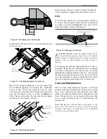
Before removing anything, place a piece of duct tape
across the cam and half nut (see
Figure 7
) to maintain
their relative position while the mechanism is apart.
Note:
If the cam should come loose during assembly,
see
Appendix 2
for instructions on re-installing it in the
correct orientation.
Remove the tee shoulder screw, the tee and the tee washer.
Remove the spring nut, washer and quick-release spring
on the back of the mechanism. Unfasten the screw
holding the quick-release lever in place.
Do not
remove
the quick-release shaft.
Remove the two guide rod screws and carefully pull
the front plate off. The fi t between guide rods and front
plate is tight; you may need to progressively tap each
side until these come apart. Avoid skewing the front
plate in relation to the guide rods.
From this point on, the installation of the vise mechanism
will be much easier if the workbench is fl ipped upside
down. Alternatively, if your workbench top is easily
removable, just detach it from the base and fl ip it over.
The vise mechanism weighs more than 20 lb and it
is much easier to locate it and screw it in place when
gravity is on your side.
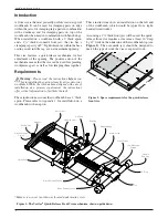
Figure 7: Removing the front plate prior to installation.
5
Veritas
®
Quick-Release Front Vise
Set Screws
(not visible)
Tape to hold half nut
and cam in position.
Guide Rod
Main Screw
Cover
Front Plate
Guide Rod
Screw
Main Screw
Thrust Washer
Tee
Shoulder
Screw
Tee
Tee Washer
Quick-Release
Lever Screw
Quick-Release
Lever
Quick-Release Shaft
Quick-Release
Spring
Back Plate
Spring Nut
Washer


