manualshive.com logo in svg
background image

Z206792-0B 

Page 16 of 24 

©2014 Veris Industries   USA 800.354.8556 or +1.503.598.4564  / [email protected] 04142 

Alta Labs, Enercept, Enspector, Hawkeye, Trustat, Aerospond, Veris, and the Veris ‘V’ logo are trademarks or registered trademarks of  Veris Industries, L.L.C. in the USA and/or other countries.

Other companies’ trademarks are hereby acknowledged to belong to their respective owners.

Installation Guide

Power Monitoring

E30E Series

TM

Using the GUI to Set the Configuration Parameters for the Communication Protocols

Access the GUI according the instructions in the “Accessing the Graphical User Interface (GUI)” section.

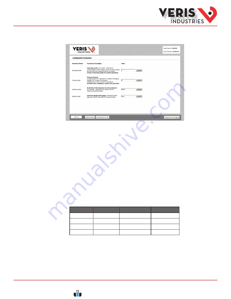
The home screen on the GUI provides fields for configuration of the E30E. The E30E has four primary modes of operation, each of 
which support a different combination of protocols. Each option field has a Submit button to the right. When changing the value 
in any field, click Submit to store the new value. The GUI prompts the user to restart the system. If multiple values are changed, 
it is easiest to submit all changes and restart only once when finished with the whole screen. To restart, click the System Restart 
button in the row at the bottom of the screen. The restart takes several seconds, during which the server may lose its connection. 
Messages appear at the top of the screen indicating current status, but do not perform any actions. Simply allow the tool to 
complete the restart cycle. 

The first selection in the GUI is Operating_Mode, which has two choices:

1. Locked:  used for all normal product operation. It is provided as a tool for high-level technical support. The gateway retains 
its current profile configuration when powered. 
2. Discovery mode (default):  deletes profiles and rediscovers them when the device is powered again. The results are the same, 
unless the profile configuration is intentionally altered. Profile selection and discovery are especially important when using 
BACnet or SNMP protocols. For normal operation, always use discovery mode.

The second selection in the GUI is Protocol_Mode, used to select the combination of protocols the product communicates with. 
The E30E supports five protocols, some of which can operate simultaneously. The table below shows what protocols are supported 
in each mode.

Protocol Mode

Primary Protocol

Ethernet Protocol

RS-485 Protocol

1

BACnet MS/TP

Modbus TCP

BACnet MS/TP

2

BACnet IP

BACnet IP/Modbus TCP

Modbus RTU

3

SNMP

SNMP/Modbus TCP

Modbus RTU

4

Modbus

Modbus TCP

Modbus RTU

To select a primary protocol mode, enter the corresponding number into the text field adjacent to the Primary Protocol option 
and click the Submit button to the left of the text field. A prompt appears at the top of the screen instructing the user to restart 
the system. When finished, the screen refreshes itself with the appropriate fields for the selected mode. 

The next GUI selection, in any protocol mode, is the Upstream_Baud rate selection. If you have selected BACnet MS/TP (mode 1) as 
the primary protocol mode, this value sets the MS/TP baud rate. If you have selected modes 2 or 3 as the primary protocol mode, 
you may not be using the RS-485 interface at all. If so, this setting can be ignored.

If you have selected BACnet IP, SNMP or Modbus mode, the next selection is Modbus_Parity, which sets the parity of the upstream 
serial connection. If using Modbus RTU protocol, set this to match your Modbus master. If not, ignore this field.

Gateway 
Configuration (cont.)

www.calcert.com

[email protected]

1.888.610.7664

0

5

10

15

20

25

30

Содержание E30A042

Страница 1: ...d avoid the hazards involved NEC2011 Article 100 No responsibility is assumed byVeris Industries for any consequences arising out of the use of this material DANGER Product Identification Product Over...

Страница 2: ...ency 2560 Hz Update Rate Modbus 1 8 seconds both panels BACnet 14 seconds SNMP 20 seconds ETHERNET COMMUNICATION Physical Interface RJ45 connector with 10 100 Mbit Ethernet Protocols Supported Modbus...

Страница 3: ...enter 16 4 417 mm 1 7 43 mm 0 4 10 mm opening 0 7 18 mm on center 2 0 50 mm 1 3 32 mm 15 7 399 mm 0 4 10 mm opening 0 7 18 mm on center 1 3 32 mm 12 3 312 mm 0 4 10 mm opening 0 7 18 mm on center 0 9...

Страница 4: ...g and power calculations 6 Control Mains Power Connection Easy 2 wire 100 277 VAC 50 60 Hz connection 7 Auxiliary Inputs These 0 333 VAC inputs are used for monitoring the main breaker or other high a...

Страница 5: ...3 6 1 4 1 40845 1 30 1 1 6 3 4 0 For models with 42 channels or more these features are configured independently for each panel Logical Circuit support The E30E can be configured to map any set of 1...

Страница 6: ...r phase Voltage L L multi phase average and per phase Voltage L N multi phase average and per phase Frequency phase A Demand Measurements Current present demand multi phase average and per phase Real...

Страница 7: ...circuit numbers in the field during commissioning by writing to Modbus Register 6 or use the free configuration software at www veris com The examples in this graphic show the 21 current sensor strips...

Страница 8: ...grounding connection is located on the housing see below Use this stud to ground the device when it is mounted on a nonconductive surface CURRENT SENSOR STRIP CURRENT SENSOR STRIP CURRENT SENSOR STRI...

Страница 9: ...the E3x Configuration Tool to view the phase angles of active circuits to help verify that those circuits are connected to and mapped to the proper voltage phases See the E3x Commissioning Guide www...

Страница 10: ...nd termination the value and placement of these resistors varies for each standard The E30E does not implement any RS 485 line polarization bias or termination internally For the RS 485 cable use shie...

Страница 11: ...ed to work on the network and is being accessed from a PC on that same network open a web browser and enter the IP address of the E30E into the address URL field on the browser Press enter The GUI lau...

Страница 12: ...et to its factory default IP address of 192 168 1 24 set the PC to an unused static IP address on the 192 168 1 xxx subnet where xxx is any value between 1 and 255 except 24 Set the subnet mask to 255...

Страница 13: ...se the following IP Address Make note of the IP address that appears then enter the static IP address e g if the E30E Series is still set to its default address of 192 168 1 24 then change it to 192 1...

Страница 14: ...s Installation Guide Power Monitoring E30E Series TM UsingtheGUItosetuptheIPaddressforuseonyournetwork 1 Access the GUI according the instructions in the Accessing the Graphical User Interface GUI sec...

Страница 15: ...IP Address Settings menu b Enter the desired IP address in the N1_IP_Address field in the format xxx xxx xxx xxx c If necessary change the Subnet Mask by entering the appropriate new value in the N1_N...

Страница 16: ...iscovery mode default deletes profiles and rediscovers them when the device is powered again The results are the same unless the profile configuration is intentionally altered Profile selection and di...

Страница 17: ...MS TP trunk and any devices beyond it This virtual router creates an exclusive BACnet network on which the meter s BACnet devices reside This network must have a BACnet network number that is differen...

Страница 18: ...eters described above for BACnet MS TP mode One additional parameter BACnet_IP_Port is used to set the UDP port Most BACnet systems use the default port 47808 decimal 0xBAC0 hex that is recommended in...

Страница 19: ...two unique parameters The SNMP_Community string is used to control access to the device Whatever value entered must be used in the MIB browser or SNMP access software to communicate with this device...

Страница 20: ...on settings using the GUI Valid network numbers range from 1 to 65534 if other values are entered the network number defaults to 5 b Device_ID Offset Every BACnet device must have a BACnet Device_ID n...

Страница 21: ...WP B K 1 10 BIBB Data Sharing WritePropertyMultiple B DS WPM B K 1 12 BIBB Data Sharing COV B DS COV B K 2 2 BIBB Alarm and Event Notification Internal B AE N I B K 2 5 BIBB Alarm and Event ACK B AE...

Страница 22: ...property The E30E supports Subscribe_COV with default COV increment values assigned as shown in the data object tables If these values are not appropriate for a specific application write them as nee...

Страница 23: ...ected to the Panel 1A and Panel 1B connectors and to the data set under Modbus address 1 or BACnet device identified as Node_1 in the GUI Panel 2 corresponds to the branch current sensor strips connec...

Страница 24: ...ctual strip installation Verify phase rotation of breakers firmware rev 1 012 or higher allows for custom rotation if needed Current reading is not as expected or reading is on different CT number tha...

Отзывы: