VERAZ NETWORKS I-Gate 4000 PRO Скачать руководство пользователя страница 36

Cabinet  Instal lation  

I-Ga te 4000 P R O Ins tall ation 

5-6 

Veraz Networks Inc. Proprietary 

02041802-05 

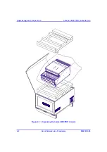
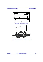
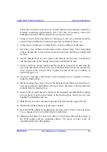
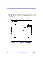
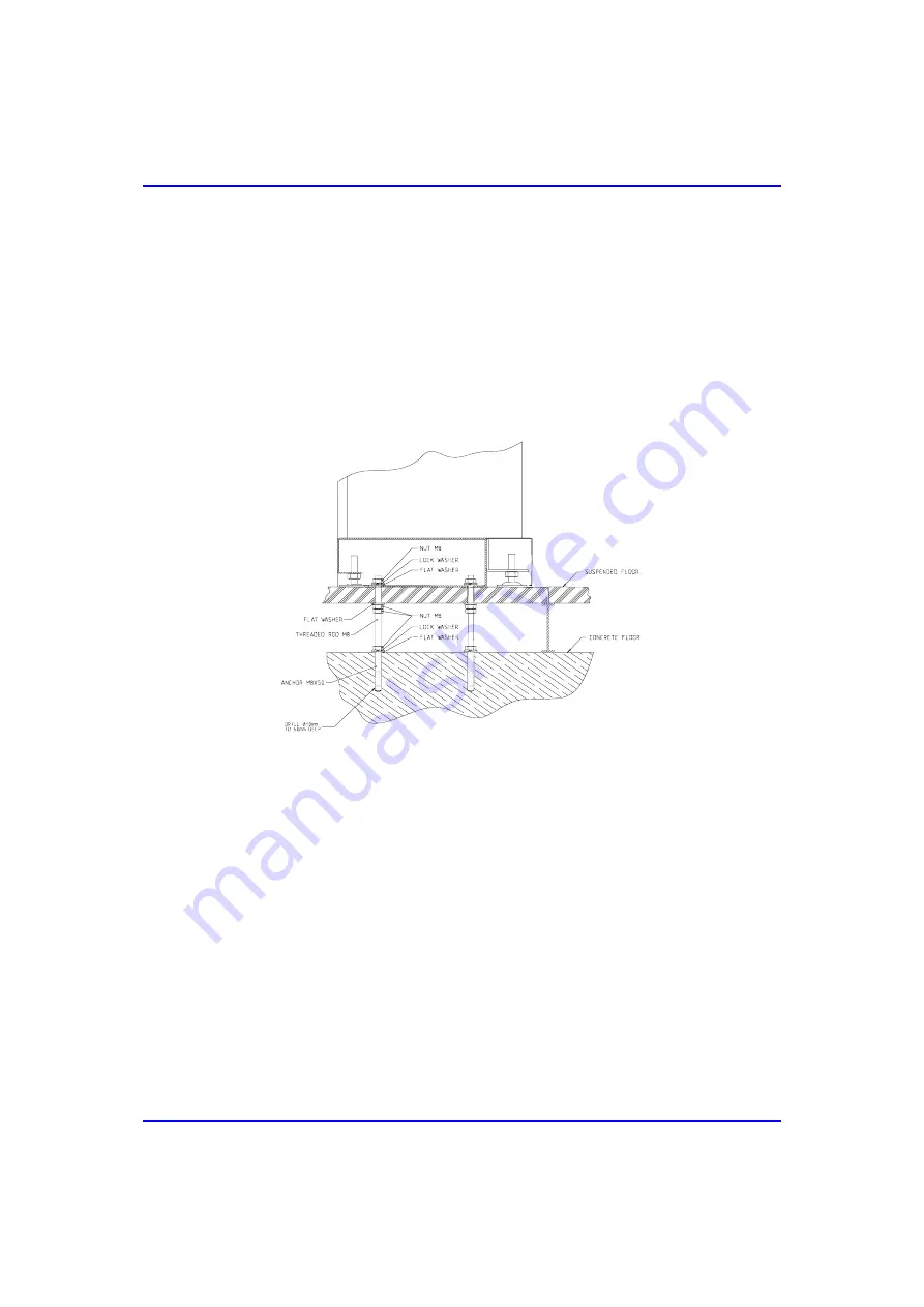
17. Tighten the nuts, including the flat washers and the spring washers, of the screw 

anchors. Make sure that the ETSI cabinet remains level. If necessary, repeat the 
leveling and tightening procedures. 

18. Connect the grounding cable, using the appropriate screws, to the underside of 

the ETSI cabinet. 

19. Complete the leveling and tightening of the remaining ETSI cabinets, as 

described above. Ensure that the cabinets are flush with one another. 
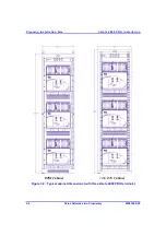
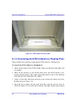
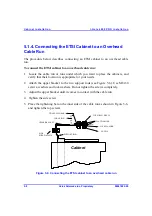
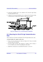
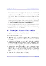
 

Figure 


5-4:  Bolting the ETSI cabinet to a floating floor  

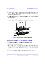
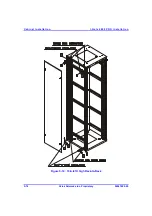
5.1.3. Connecting the ETSI Cabinet to a Wall 

The procedure below describes connecting an ETSI cabinet to a wall. 

To connect the ETSI cabinet to a wall: 

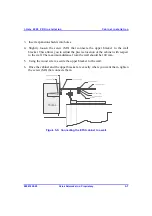
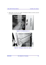
1.  Mark out the wall in each equipment room for the location of the cabinet. Use 

the upper bracket (see Figure  5-5) for locations of holes to be made in a concrete 
or brick wall. If the wall is drywall or wood, locate a wooden beam to connect 
the cabinet. 

2.  Using a 10 mm drill bit, drill the mounting holes approximately 75 mm deep. 

Содержание I-Gate 4000 PRO

Страница 1: ...f f f fJ J J Jd QMMM mol d QMMM mol d QMMM mol d QMMM mol s K j OKO f j f j f j f j...

Страница 2: ...89 336 EEC Council Directive of 3 05 1989 on the approximation of laws of the Member States relating to Electro Magnetic Compatibility EMC Issue Date February 6 1996 This product is marked with a TUV...

Страница 3: ...nt or the information contained herein for any purposes other than those for which it was disclosed is strictly forbidden Any representation s in this document concerning performance of VERAZ NETWORKS...

Страница 4: ...This page intentionally left blank...

Страница 5: ...2 Power Precautions 2 2 2 3 Battery Instructions 2 2 2 4 Electrostatic Discharge ESD Precautions 2 4 2 5 Radio Interference Precautions 2 5 2 6 Tool List 2 6 3 Planning Installation Site 3 1 3 1 Physi...

Страница 6: ...high Cabinet to a Floating Floor 5 11 5 2 3 Mounting the 19in 47U high Cabinets Rack to Rack 5 13 6 Installing the Chassis 6 1 6 1 Mounting Kit 6 2 6 2 Attaching the Mounting Brackets to the Chassis...

Страница 7: ...aul Card 9 15 9 7 1 Network Connection 9 16 9 7 2 External Clock Connection 9 17 9 8 ALRM Card 9 18 9 8 1 Alarm Interface Connection 9 19 9 8 2 Monitor Interface Connection 9 20 9 9 PEFU and PEFD Card...

Страница 8: ...xMS Status Manager 12 7 12 5 Transmission Tests 12 7 12 5 1 E1 DS1 Transmission Test 12 8 12 5 2 DS3 Transmission Test 12 9 12 6 Tone Connectivity Channel Test 12 10 12 7 Clear Channel Test 12 10 12...

Страница 9: ...Figure 5 8 Bolting the 19in 47U high cabinet to a concrete floor 5 11 Figure 5 9 Bolting the 19in 47U high cabinet to a floating floor 5 13 Figure 5 10 19in 47U high Rack to Rack 5 14 Figure 6 1 Moun...

Страница 10: ...igure 10 2 PDU installation 10 2 Figure 10 3 PEFU PEFD cards power cable connector 10 4 Figure 10 4 PDU installation wiring 10 4 Figure 10 5 Typical cabinet power cable connections 10 5 Figure 11 1 CO...

Страница 11: ...s to both I O connections and the cards There are no connections at the rear of the terminal Each interface card has a protective panel for physical protection and as a guard against electromagnetic i...

Страница 12: ...re presented in the order in which the procedures should be carried out The instructions can also be used by the customer on site for re installation or troubleshooting 1 2 Intended Audience This manu...

Страница 13: ...rding to country national electrical codes For North America equipment must be installed in accordance with US National Electrical Code Articles 110 16 110 17 and 110 18 and the Canadian Electrical Co...

Страница 14: ...ode conductor 2 3 Battery Instructions Warning There is the danger of explosion if the battery is replaced incorrectly Replace the battery only with the same or equivalent type recommended by the manu...

Страница 15: ...econdo le istruzioni del produttore Advarsel Det kan v re fare for eksplosjon hvis batteriet skiftes p feil m te Skift kun med samme eller tilsvarende type som er anbefalt av produsenten Kasser brukte...

Страница 16: ...personal tools test equipment and metal objects that come into contact with MOS devices must be electrically grounded Any static or foreign voltage that is introduced into these devices may damage th...

Страница 17: ...with the limits for a Class A digital device pursuant to Part 15 of the FCC Rules These limits are designed to provide reasonable protection against harmful interference when the equipment is operated...

Страница 18: ...ding wires Yardstick or tape measure Wire wrap unwrap tool 8 mm and 10 mm drill bits for wood and concrete Lifting device to move the pallet mounted containers Air pressure spray 10 mm drill bit for d...

Страница 19: ...binet can accommodate up to three chassis or up to six if installed back to back in addition to air buffers and a Power Distribution Unit PDU The I Gate 4000 PRO can also be installed in other suitabl...

Страница 20: ...Planning Installation Site I Gate 4000 PRO Installation 3 2 Veraz Networks Inc Proprietary 02041802 05 Figure 3 1 I Gate 4000 PRO external dimensions...

Страница 21: ...es Depth 275 mm 10 82 inches Max Weight 38 kg when fully populated Table 3 2 I Gate 4000 PRO cabinet dimensions Cabinet Type Width Height Depth Remarks ETSI Cabinet 600 mm 23 62 in 2200 mm 86 61 in or...

Страница 22: ...ning Installation Site I Gate 4000 PRO Installation 3 4 Veraz Networks Inc Proprietary 02041802 05 ETSI Cabinet 19in 47U Cabinet Figure 3 2 Typical cabinet dimensions with three I Gate 4000 PRO termin...

Страница 23: ...I Gate 4000 PRO I Gate 4000 PRO I Gate 4000 PRO I Gate 4000 PRO I Gate 4000 PRO I Gate 4000 PRO I Gate 4000 PRO I Gate 4000 PRO I Gate 4000 PRO I Gate 4000 PRO Two cabinets back to back 1 2 meters Fig...

Страница 24: ...put Voltage 48VDC or 60VDC Nominal Power Consumption Per E1 DS1 or DS3 Gateway 800W Max PDU Circuit Breaker Per Gateway 27A 3 4 Environmental Specifications The table below lists the I Gate 4000 PRO e...

Страница 25: ...te 4000 PRO is cooled by the flow of air between the terminals mounted in the cabinet The fans and air baffles ensure that sufficient air flows between the terminals The cooling system incorporating t...

Страница 26: ...Planning Installation Site I Gate 4000 PRO Installation 3 8 Veraz Networks Inc Proprietary 02041802 05 This page intentionally left blank...

Страница 27: ...items listed in your Commercial Invoice are included in the Production Packing List 3 As you unpack the equipment visually inspect all items for damage and make sure that all listed items have been d...

Страница 28: ...Unpacking and Inspection I Gate 4000 PRO Installation 4 2 Veraz Networks Inc Proprietary 02041802 05 Figure 4 1 Unpacking the I Gate 4000 PRO chassis...

Страница 29: ...ts and personnel that come into contact with CMOS devices must be electrically grounded Note The TPSM TPSM R1 card contains a lithium battery ensure that it has been correctly inserted Replace it only...

Страница 30: ...Unpacking and Inspection I Gate 4000 PRO Installation 4 4 Veraz Networks Inc Proprietary 02041802 05 This page intentionally left blank...

Страница 31: ...tandard 19inch x 23inch wide type cabinet Section 5 2 19in 47U high Cabinet Installation however applies only to the 19in 47U high cabinet Warning The TUV certificate requires a steel or aluminum buff...

Страница 32: ...g light strokes until they protrude about 20 mm 5 Remove the washers and nuts from the anchoring screws 6 If the lower media gateway chassis is already installed remove it by unscrewing the screws on...

Страница 33: ...tallation Cabinet Installation 02041802 05 Veraz Networks Inc Proprietary 5 3 mounting holes 60 0 140 0 565 0 Front Rear A A A A Figure 5 1 ETSI cabinet base panel Figure 5 2 Bolting the ETSI cabinet...

Страница 34: ...of the ETSI cabinets Make sure that they stand flush with one another 2 Mark out the locations on the floating floor where the ETSI cabinet s screw anchors will be inserted They will be placed through...

Страница 35: ...the threaded rod Insert the top of the threaded rod with the nut into the screw anchor in the concrete floor Tighten the nuts on the screw anchors as shown in Figure 5 4 10 Screw two nuts and a flat...

Страница 36: ...f the remaining ETSI cabinets as described above Ensure that the cabinets are flush with one another Figure 5 4 Bolting the ETSI cabinet to a floating floor 5 1 3 Connecting the ETSI Cabinet to a Wall...

Страница 37: ...e location of the cabinet with respect to the wall The maximum distance from the wall should be 100 mm 5 Using the wood screw secure the upper bracket to the wall 6 Once the cabinet and the upper brac...

Страница 38: ...eir location is appropriate for your needs 2 Attach the upper bracket to the two support rods see Figure 5 6 Use M8x30 screws washers and lock washers Do not tighten the screws completely 3 Adjust the...

Страница 39: ...a Concrete Floor The procedure below describes bolting a 19in 47U high cabinet to a concrete floor To bolt the 19 in 47U cabinet to a concrete wall 1 Mark out the floor in each equipment room for the...

Страница 40: ...er the anchoring screws 8 Tighten the nuts on the anchoring screws along with the flat washer and lock washer When tightening each screw make sure that the 19in 47U high cabinet remains level 9 If you...

Страница 41: ...e locations on the floating floor where the 19in 47U high cabinet screw anchors will be inserted They will be placed through the center of the mounting holes located on the underside of the cabinet 3...

Страница 42: ...d rod with the nut into the screw anchor in the concrete floor Tighten the nuts on the screw anchors as shown in Figure 5 9 10 Screw two nuts and a flat washer on the threaded rod to a height of 20 mm...

Страница 43: ...OR LEVEL Figure 5 9 Bolting the 19in 47U high cabinet to a floating floor 5 2 3 Mounting the 19in 47U high Cabinets Rack to Rack The procedure below describes mounting the 19in 47U high cabinets rack...

Страница 44: ...Cabinet Installation I Gate 4000 PRO Installation 5 14 Veraz Networks Inc Proprietary 02041802 05 Figure 5 10 19in 47U high Rack to Rack...

Страница 45: ...or 19in 47U cabinet the cabinet must first be bolted to the floor see Chapter 5 Cabinet Installation The procedure for mounting the chassis is the same for both the ETSI 45U 54U and 19in 47U cabinet e...

Страница 46: ...alling an I Gate 4000 PRO chassis into a cabinet These mounting kits depend on the cabinet in which the I Gate 4000 PRO is to be installed e g ETSI 19in 47U or 45U 54U cabinets These mounting kits con...

Страница 47: ...TIC WASHER M6 WASHER M6 Figure 6 2 Positioning of mounting brackets The mounting position in Figure 6 2 allows the mounting pin to support the chassis while the mounting hardware is being attached to...

Страница 48: ...tach the second mounting bracket to the side of the I Gate 4000 PRO 6 3 Inserting the Chassis into the Cabinet Once you have attached the mounting brackets to the I Gate 4000 PRO chassis you can inser...

Страница 49: ...ssis 02041802 05 Veraz Networks Inc Proprietary 6 5 5 Repeat steps 2 to 4 for every chassis Remember to make room for the network external switch shelf and the PDU Figure 6 3 Inserting a chassis nut F...

Страница 50: ...Installing the Chassis I Gate 4000 PRO Installation 6 6 Veraz Networks Inc Proprietary 02041802 05 This page intentionally left blank...

Страница 51: ...ing system Later however you can remove the fan tray to replace the entire fan tray as needed Figure 7 1 Two Fan Tray units installed in the I Gate 4000 PRO The Fan Tray shelf see Figure 7 2 is locate...

Страница 52: ...of the system cards have a heat sensor If the temperature threshold is exceeded in any one of the cards an alarm is sent to the TPSM TPSM R1 controller which instructs the fans to operate at a higher...

Страница 53: ...or rear view Table 7 2 lists the fan specifications Table 7 2 Fan specifications Specification Measurement Fan size 3 62 square x 1 50 deep 92 mm x 38 mm Rated voltage 24 VDC Operating Voltage 14 27 7...

Страница 54: ...LED alarm indication red you must replace the entire fan tray in which the failed fan resides To replace a fan tray 1 Loosen the two fasteners that connect the failed Fan Tray Unit to the I Gate 4000...

Страница 55: ...t chassis 8 1 Card Description and Layout The I Gate 4000 PRO is encased in a 32 slot chassis which provides two shelves of slots for inserting cards upper and lower shelf Each shelf contains 16 slots...

Страница 56: ...Inserting the Cards I Gate 4000 PRO Installation 8 2 Veraz Networks Inc Proprietary 02041802 05 Figure 8 1 I Gate 4000 PRO media gateway shelf...

Страница 57: ...nd D3MC redundancy D3MC redundancy ST1I 19 20 29 30 TDM STM 1 OC 3 interface ST1M TPSI 23 26 for redundancy Interface with external IP based packet switching networks ext clock VoIP NMS TPSM TPSE 23 2...

Страница 58: ...SPK R1 1 6 8 9 11 16 Ports for G 711 uncompressed traffic see Notes Lower Main DSPK 1 6 8 9 11 16 1 248 ports for G 711 uncompressed traffic Notes adhere to the following card combination consideratio...

Страница 59: ...rd only if all DSP type active cards are DSPK cards When TPSM is installed each DSPK and each DSPK R1 i e 100BaseT handles up to 1 248 channels When TPSM R1 is installed each DSPK R1 handles up to 1 4...

Страница 60: ...S1 Interface Table 8 2 lists the cards in an example of an E1 DS1 interface Figure 8 2 shows a typical card setup Figure 8 2 E1 DS1 Interface I O cards in upper shelf Main cards in lower shelf Table 8...

Страница 61: ...ple for DS3 Interface Table 8 3 shows the cards in an example of a DS3 interface Figure 8 3 shows a typical card setup Figure 8 3 DS3 Interface I O cards in upper shelf Main cards in lower shelf Table...

Страница 62: ...OC 3 Interface Table 8 4 shows the cards in an example of an STM 1 OC 3 interface Figure 8 4 shows a typical card setup Figure 8 4 STM 1 OC 3 Interface I O cards in upper shelf Main cards in lower sh...

Страница 63: ...ecure the I Gate 4000 PRO front lower panel to the chassis Do not use pliers the fasteners should only be tightened or loosened by hand 2 Swing the front panel open and allow it to hang on its hinges...

Страница 64: ...as possible 2 Close top and bottom ejectors Figure 8 5 Removing inserting a Main card 5 Perform a reset of the I Gate 4000 PRO either by pressing the RESET button on the front of the TPSM TPSM R1 card...

Страница 65: ...stops Do not force the card 3 Press the card s PCB ejector into the closed up position to seat the card 4 Confirm that the card is aligned flush with the other cards in the upper shelf 5 Tighten the c...

Страница 66: ...Inserting the Cards I Gate 4000 PRO Installation 8 12 Veraz Networks Inc Proprietary 02041802 05 This page intentionally left blank...

Отзывы: