
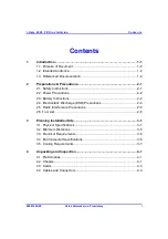

Conten ts
I-Ga te 4000 P R O Ins tall ation
vi
Veraz Networks Inc. Proprietary
02041802-05
Figure 9-1: D16I card - front panel ...................................................................... 9-2
Figure 9-2: D3IO card - front panel...................................................................... 9-4
Figure 9-3: ST1I card - front panel ...................................................................... 9-5
Figure 9-4: TPSI card's front panel...................................................................... 9-6
Figure 9-5: TPSE front panel............................................................................... 9-9
Figure 9-6: TPSO card's front panel .................................................................. 9-12
Figure 9-7: TPSL card's front panel................................................................... 9-15
Figure 9-8: ALRM card's front panel.................................................................. 9-18
Figure 9-9: PEFU/PEFD cards .......................................................................... 9-21
Figure 10-1: Typical PDU configuration, three-dimensional view....................... 10-1
Figure 10-2: PDU installation ............................................................................ 10-2
Figure 10-3: PEFU/PEFD cards power cable connector.................................... 10-4
Figure 10-4: PDU installation wiring .................................................................. 10-4
Figure 10-5: Typical cabinet power cable connections ...................................... 10-5
Figure 11-1: COM1 Properties dialog box ......................................................... 11-3
Figure 12-1: I/O cards in upper shelf (example of E1/DS1 interface)................. 12-3
Figure 12-2: Main cards in the lower shelf (example of E1/DS1 interface)......... 12-3
Figure 12-3: I/O cards in upper shelf (example of DS3 interface) ...................... 12-4
Figure 12-4: Main cards in the lower shelf (example of DS3 interface) .............. 12-4
Figure 12-5: E1/DS1 Transmission test setup ................................................... 12-8
Figure 12-6: DS3 Transmission test setup ........................................................ 12-9
Figure 12-7: Veraz Networks Field Activity Certificate for VoIP products......... 12-17


