VEMAG HP10E Скачать руководство пользователя страница 55

HP10E / HP12E / HP15E / HP20E - Dairy design

6. Graphical control

6-17

© VEMAG 2013

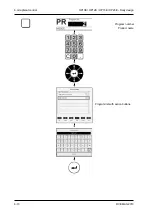
6.5.4 Select start/stop method

In the 

Start/stop method

 field you can select the start/stop method and 

the attachments used.
•  Press the 

Start/stop method

 key.

•  Select the 

Start/stop method

 field using the cursor key.

•  Press 

Enter.

 A list of the possible start/stop methods is displayed.

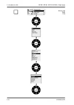
•  Select the start/stop method using the 

cursor keys

.

•  Press 

Enter

.

•  Select the 

Attachment / Optional

 field using the cursor key.

•  Press 

Enter.

 A list of the possible attachments / options is displayed.

•  Select the attachment / option using the 

cursor keys

.

•  Press 

Enter

.

Содержание HP10E

Страница 1: ...Vacuum filler HP10E Dairy design from 168 1004 HP12E Dairy design from 168 5003 HP15E Dairy design from 168 2010 HP20E Dairy design from 168 3009 Operating instructions...

Страница 2: ...yment of damages All rights reserved in the event of the grant of a patent utility model or ornamental design registration We reserve the right to make technical modifications Issue 04 13 Version 2 4...

Страница 3: ...ble screws 4 3 4 4 Fitting the filling horn holder 4 4 4 5 Setting the vacuum 4 5 4 5 1 Filling liquid products 4 5 4 6 Fitting the scraper 4 6 4 7 Adjusting the knee lever 4 7 5 Operation 5 1 5 1 Wor...

Страница 4: ...g an external signal 6 35 6 6 4 12 Linking support 6 35 Working with sausage lines 6 36 6 6 4 13 Product type 6 36 6 6 4 14 Last portion 6 36 6 6 4 15 Split casing tolerance 6 36 6 6 4 16 Remaining po...

Страница 5: ...4 External portioning 6 58 6 7 Configurations operating mode settings 6 61 6 8 Service 6 63 6 8 1 Service pages 6 63 6 9 Messages 6 64 6 9 1 List of messages 6 64 7 Cleaning 7 1 7 1 General informatio...

Страница 6: ...ge 8 19 9 Troubleshooting 9 1 9 1 General information 9 1 9 2 Troubleshooting table 9 1 10 Appendix 10 1 10 1 General information 10 1 10 2 Technical data HP10E HP12E HP15E HP20E 10 2 10 3 Dimensional...

Страница 7: ...provisions of the EC Machinery Directive 2006 42 EC Particular consideration was given to the standard EN 12463 2004 D Food Processing Machinery Filling machines and auxiliary machines Safety and hyg...

Страница 8: ......

Страница 9: ...eparate operating instructions If you have any questions which cannot be answered by this manual please contact VEMAG Customer Service at any time Our staff will be please to hear your suggestions Rea...

Страница 10: ...HP10E HP12E HP15E HP20E Dairy design 0 Foreword 0 2 VEMAG 2013...

Страница 11: ...atures between 0 5 C and 25 C The vacuum filler is designed for one operator The operator must have been trained on site by VEMAG specialists or one of their representa tives The vacuum filler may onl...

Страница 12: ...This warning symbol refers to important instructions which must be follo wed to prevent faulty operation which could pose a threat to human life or lead to injury Warning This warning symbol refers to...

Страница 13: ...mainte nance department or VEMAG Customer Service informed The machine may not be operated without the housing cover Route mains cables and data cables e g remote control cable so as to avoid tripping...

Страница 14: ...starting up the machine always perform the following steps Check that the machine is in proper condition Leaking oil indicates leaks which must be eliminated immediately In this case inform your in h...

Страница 15: ...he hopper is open Danger To prevent injury switch off the machine before doing any work on the hopper Then switch off the main switch to disconnect the machine from the mains Do not climb onto the mac...

Страница 16: ...that the product is conveyed gently and evenly to the outlet The same volume is conveyed with each rotation of the dou ble screws In this process the proportion of air in the product for filling is re...

Страница 17: ...d this is locked at the outlet by the locking nut 2 Further attachments optional can be connected to the filling horn holder The product is ejected through the filling horn holder by the double screws...

Страница 18: ...connected to the power supply of the machine via equipment socket 2 Instead of blind covers further sockets can be provided for supplementary equipment like coextrusion systems optional for example 1...

Страница 19: ...display 4 Vacuum control valve Fig 2 7 Machine control panel 1 2 3 4 ON key This key switches on the drive of the machine OFF key This key switches off the drive of the machine Vacuum display The vacu...

Страница 20: ...ll the hopper or get at it for cleaning and maintenance purposes Danger There is a risk of crushing when folding the step in and out Proceed with extreme caution when folding the step in and out to pr...

Страница 21: ...a capacity of at least 1 500 kg If at all possible move the fork lift lifting truck under the machine from the outlet side Danger Never tilt the machine when transporting it and when setting it up al...

Страница 22: ...fork 1 is located precisely centrally between the feet Warning Place planks 2 between the fork and the machine to prevent the machi ne slipping during transportation You must ensure that the fork and...

Страница 23: ...nner 2 If necessary the adjustable feet must be used to compensate for any unevenness in the floor until the machine is absolutely level The outlet height of the machine is 1 000 mm as standard It can...

Страница 24: ...trical connection may be made only by authorised specialist staff or specialist companies Inside the machine housing connect the machine to the main switch 1 of the machine using four core cable with...

Страница 25: ...e vacuum pot Take hold of the float valve on valve body 1 and pull it horizontally off the vacuum line 1 Valve body Fig 3 6 Float valve 1 Warning Do not take hold of the float valve at the bottom at t...

Страница 26: ...HP10E HP12E HP15E HP20E Dairy design 3 Installation and commissioning 3 6 VEMAG 2013...

Страница 27: ...nect the machine from the mains 4 2 Fitting the double screw housing Danger There is a risk of crushing when fitting and removing the double screw housing and the double screws To prevent injury proce...

Страница 28: ...Setting up 4 2 VEMAG 2013 A pin 1 under the coupling pins 2 in the feed cylinder centres the dou ble screw housing which has the appropriate bore on its end face 1 Centring pin 2 Coupling pins Fig 4 2...

Страница 29: ...on in relation to the coupling pins in the feed cylinder by turning the double screws 2 in opposite directions 1 Slots 2 Double screws Fig 4 3 Lining up the double screws 2 1 Push double screws 1 into...

Страница 30: ...is between the 10 and 11 o clock position and insert filling horn holder 2 Turn locknut 1 clockwise to lock the filling horn holder The handle should now be approximately vertical 1 Locking nut 2 Fill...

Страница 31: ...vacuum has been set down If the vacuum is not correct the vacuum pump may be destroyed If the vacuum pump takes in product or water as a con sequence of the vacuum not correctly set it is essential t...

Страница 32: ...f the hopper Danger There is a risk of crushing when fitting and removing the scraper To prevent injury proceed extremely carefully when fitting and dismantling the part Inspect the scraper for residu...

Страница 33: ...erator Undo the hexagonal nut 1 using the universal spanner 2 Adjust the knee lever to the desired height H and angle W Tighten up the hexagonal nut again Move the knee lever plate 3 along the lever s...

Страница 34: ...HP10E HP12E HP15E HP20E Dairy design 4 Setting up 4 8 VEMAG 2013...

Страница 35: ...he machine Press the ON switch on the machine control panel Danger You must check that any safety devices are working properly Unlock the hopper and tip it open Remove the filling horn holder In each...

Страница 36: ...escapes at the outlet This prevents the pumping element running dry When filling hot pro ducts wait about 1 minute to start production This ensures that all machine parts which come into contact with...

Страница 37: ...k of crushing dragging in and burns Proceed with extreme caution and do not reach into the inside of the machine Press the OFF key on the machine control panel Switch off the main switch of the machin...

Страница 38: ...HP10E HP12E HP15E HP20E Dairy design 5 Operation 5 4 VEMAG 2013...

Страница 39: ...al control 6 1 VEMAG 2013 6 Graphical control This section introduces the individual controls of the graphical control system How is the control panel arranged How is the screen arranged What function...

Страница 40: ...HP10E HP12E HP15E HP20E Dairy design 6 Graphical control 6 2 VEMAG 2013 Colour screen Keypad Function keys...

Страница 41: ...keys are integrated in the green control panel The screen is divided into various fields Section 6 2 There are seven function keys to both the left and the right of the screen which you use to activat...

Страница 42: ...HP10E HP12E HP15E HP20E Dairy design 6 Graphical control 6 4 VEMAG 2013 Header Program Product name Parameters Footer Parameters Mode group Mode View Start stop method...

Страница 43: ...on the left hand side of the screen Section 6 5 1 The mode group top mode centre view bottom and start stop method are displayed on the right hand side of the screen Section 6 5 2 A function key is a...

Страница 44: ...HP10E HP12E HP15E HP20E Dairy design 6 Graphical control 6 6 VEMAG 2013 Numerical keypad Key C Cancel Screen up down keys Cursor keys Enter key Plus minus keys Padlock key...

Страница 45: ...key The padlock key performs the following functions Open program locking userkey You can use program locking to block entry for almost all parameters You can use the userkey to block release access t...

Страница 46: ...nds of message Fault red and white Fault eliminated blue and white Warning on display yellow and black Service message on display yellow and black Information on display white and blue Standby indicat...

Страница 47: ...ers the principles of operating the portioning computer How are programs selected and edited How are programs imported and exported with the aid of a USB stick How are the mode group mode view and sta...

Страница 48: ...HP10E HP12E HP15E HP20E Dairy design 6 Graphical control 6 10 VEMAG 2013 Program number Product name Program list with action buttons...

Страница 49: ...ical keypad Press Enter Select the field for product name using the bottom cursor key Press Enter A list of the existing programs appears Below the list are six keys for selecting the desired action N...

Страница 50: ...HP10E HP12E HP15E HP20E Dairy design 6 Graphical control 6 12 VEMAG 2013 USB stick plugged in detected Load recipes...

Страница 51: ...Importing and exporting programs using a USB stick You can import and export filling programs using a USB stick The USB stick is plugged into the rear of the control board Plug in USB stick The stick...

Страница 52: ...HP10E HP12E HP15E HP20E Dairy design 6 Graphical control 6 14 VEMAG 2013 Mode group Mode View...

Страница 53: ...unction key Select the Operating mode group field using the cursor key Press Enter A list of the possible mode groups is displayed Select the mode group using the Cursor keys Press Enter Select the Op...

Страница 54: ...HP10E HP12E HP15E HP20E Dairy design 6 Graphical control 6 16 VEMAG 2013 Start stop method Attachment Optional Attachment...

Страница 55: ...the Start stop method key Select the Start stop method field using the cursor key Press Enter A list of the possible start stop methods is displayed Select the start stop method using the cursor keys...

Страница 56: ...HP10E HP12E HP15E HP20E Dairy design 6 Graphical control 6 18 VEMAG 2013...

Страница 57: ...or key Press Enter Select settings using the cursor keys Press Enter Use the corresponding function key to select the language for the screen to display Press the Language function key Press Enter A l...

Страница 58: ...HP10E HP12E HP15E HP20E Dairy design 6 Graphical control 6 20 VEMAG 2013...

Страница 59: ...by accident you should set up the Program locking user type You need to log on as a Service user to do this Press the padlock key Select user Service by using the relevant password Press Enter Press...

Страница 60: ...HP10E HP12E HP15E HP20E Dairy design 6 Graphical control 6 22 VEMAG 2013...

Страница 61: ...stop methods and parameters This section introduces the various mode groups modes start stop methods and parameters What mode groups are there What modes are there What start stop methods are there W...

Страница 62: ...The feed element runs when the knee lever is actuated briefly The feed element stops when the knee lever is actuated again 6 6 2 3 Remote end The filler is actuated by an attachment via the remote co...

Страница 63: ...clipper are explained in the sections which follow 6 6 3 1 Weight Display Weight Unit Gramme g Resolution 0 1 g 1 g Setting range 1 99 999 g Application All applications not for mode group Fill Enter...

Страница 64: ...s until the machine is restarted by the knee lever or by remote control A tick should be placed next to always by pressing the Enter key if an addition is always to be made to the first portion In thi...

Страница 65: ...nding on the parameters in Section 6 6 3 5 If selecting individual portions you need to activate the knee lever signal for each portion AC signal 6 6 3 5 Linking clip time knife output signal Display...

Страница 66: ...duced maximum possible speed is adjusted automatically Only actual speed is reduced small grey number in the display If the speed is controlled by an attachment external speed control you can enter a...

Страница 67: ...0 120 g for DP machines Application When switched on back suction prevents the product running on once a portion has ended Enter back suction quantity Entering 0 switches off the parameter Press Ente...

Страница 68: ...ssure control Display Pressure control Unit Bar bar Resolution 0 1 bar Setting range 0 1 20 bar per analogue input Application All applications requiring a constant filling pressure Enter feed pressur...

Страница 69: ...nter speed of feed unit screw Press Enter The speed of the feed unit screw is adjusted automatically as a function of the feed element If required you can adapt speed infinitely using this parameter I...

Страница 70: ...set Press Enter Start linking clipper knife before or after end of portion Pause time is adapted automatically here Advance is limited by speed and portion size 0 means linking clipping or cutting at...

Страница 71: ...p counter is active if a value greater than zero is entered The stop counter has two functions 1 Stopping and resetting the counter as soon as the selected number of pieces is reached default 2 Stoppi...

Страница 72: ...speed 6 6 4 10 Vacuum control Display Vacuum control Selection Off Time Vacuum deactivated Unit Seconds sec Milliseconds ms Resolution 0 1 sec 1 ms 1 ms Setting range 0 1 25 5 sec 0 99 999 ms default...

Страница 73: ...d portioning controlled by machine downstream optional Enter number of portions and number of signals Press Enter Signal processing opens a window with the corresponding values for diagnostic purposes...

Страница 74: ...range 1 100 0 Off Application LPG 208 LPG 209 Enter value in per cent up to which the last portion is to be filled Press Enter 6 6 4 15 Split casing tolerance Display Burst tolerance Selection Off Val...

Страница 75: ...still to be produced once casing end detection is triggered 0 The current portion is broken off 1 Ignore sensor Tick the manual field if further portions are to be produced after the machine has been...

Страница 76: ...ue is the sum of sausage length 1 x 1 Example Calibre 22 mm Sausage length 270 mm Correction value bottom limit for the sausage length 270 1 x 1 269 mm Section 6 6 4 19 6 6 4 19 Portion length first p...

Страница 77: ...6 6 4 22 Cut quantity Display Cut quantity Unit Number Resolution 1 Setting range Off 1 10 Application FSL 210 Enter the number of sausages between the cuts e g 3 if sections with three sausages are t...

Страница 78: ...automatically in millimetres and displayed following entry of weight and calibre Sausage length can be altered manually 6 6 4 25 Distance from LPV 802 Display Distance Unit Millimetre mm Resolution 1...

Страница 79: ...es on each hook all loops on the smoke stick are the same once the machine has stopped e g via natural casing end detection Catch residue Sausages per hook parameter is only taken into con sideration...

Страница 80: ...Application AH 204 AH 212 The number of sausages per stick is calculated automatically and displayed Sausages per stick hooks per stick 1 x sausages per hook sau sages before first hook sausages last...

Страница 81: ...ang between the last hook of the previous stick and the first hook of the next stick For LPG and synchronizing FSL only a multiple of the sausage length can be entered Where the FSL runs continuously...

Страница 82: ...ook Display Extra hook Unit Number Resolution 1 Setting range 0 10 Application AH 204 AH 212 Enter the number of extra hooks still to be cycled after actuation of the knee lever Press Enter Extra hook...

Страница 83: ...play Last hook later Unit Millisekunden ms Resolution 1 ms Setting range 0 999 ms Application AH 204 AH 212 Enter a delay for the last hook of any stick Press Enter A delay for the last hook is requir...

Страница 84: ...is to open at the end of a line end of a casing 6 6 4 39 Separation interval Display Separation interval Unit Number Resolution 1 Setting range 0 99 Application Portioning with automatic separation v...

Страница 85: ...valve is to be open during straight filling The separation valve remains open until the weight entered has been filled Press Enter 6 6 4 42 Separation valve closed Display Separation valve closed Uni...

Страница 86: ...ks to be produced simultaneously Total weight is calculated automatically and displayed The correction value can be entered in grams under Total weight Section 6 6 3 3 6 6 4 44 Group position Display...

Страница 87: ...300 g The first portion has a weight of 300 g and is produced a total of five times You can enter up to 25 group portions If the last portion of a frame e g No 5 is 0 the next frame is displayed No 6...

Страница 88: ...ronised The speed reflects a voltage value e g 10 1 V The name for analog output 1 can be edited on the View page 6 6 4 48 Belt control analog output 2 Display Analog output 2 general applications low...

Страница 89: ...lication VEMAG scale 877 Enter sample interval Press Enter If 0 was selected the control system automatically calculates the sam ple interval If the machine is stopped as there is no sample has been a...

Страница 90: ...ch casing pusher on or off Press Enter If you activate this parameter the filling machine stops when it reaches the end of the casing The thrust of the casing feed can be set between 0 and 100 6 6 4 5...

Страница 91: ...sequent machine is not ready Start instruction The signal becomes active when starting using the knee lever or remote C also when the main drive must continue to wait e g starting the subsequent machi...

Страница 92: ...bar depending on the machine Application Separation grinder 982 separation attachment 801 Enter max filling pressure which when reached will cause the machine to stop Press Enter This function monitor...

Страница 93: ...fter the alarm is sounded before the machine stops Press Enter This function monitors temperature in separation grinder 982 separation attachment 801 Current temperature is displayed in degrees Celsiu...

Страница 94: ...level Display Hopper level Unit Per cent Resolution 1 Setting range 5 98 control range 3 to 30 Application Vacuum hopper 149 Enter hopper level Press Enter Automatic filling of the vacuum hopper is s...

Страница 95: ...he hopper is automatically filled when the filling level is undershot lower limit When the upper limit is reached filling stops only possible with external hopper filling Signal Stop if the level is u...

Страница 96: ...which the choice of filling speed is to be restricted Enter the speed limit Press Enter 6 6 4 64 External portioning Display External portioning Unit Gram g Resolution 1 g Setting range 0 Off 99999 Ap...

Страница 97: ...HP10E HP12E HP15E HP20E Dairy design 6 Graphical control 6 59 VEMAG 2013...

Страница 98: ...202 AH 204 AH 212 DM 206 AH 204 AH 212 LPG 208 AH 204 AH 212 LPG 208 Servo P AH 204 AH 212 LPG 208 Servo LPG 209 FSL 210 FSL 211 AH 204 AH 212 FSL 210 CAN FSL 211 CAN AH 204 AH 212 Portioning Filling...

Страница 99: ...hical control 6 61 VEMAG 2013 6 7 Configurations operating mode settings Different configurations can be selected depending on operating mode group and operating mode A grinder can be selected in all...

Страница 100: ...HP10E HP12E HP15E HP20E Dairy design 6 Graphical control 6 62 VEMAG 2013...

Страница 101: ...a note of the current version numbers so that you can quote them in the event of a VEMAG Customer Service query The operating hours which have been clocked up are shown at the bottom of the page Warn...

Страница 102: ...drive The feed system drive has an oil leak Dairy Eliminate the oil leak 350 F5 vacuum pump eleva tor transformer Monitoring module F5 has found overheating at the vacuum pump hoist unit or power tran...

Страница 103: ...led At the start of pressure control the pipe system is filled slowly 403 Product temperature Product temperature outside set range Reduce or increase product tem perature 404 Tighten up union nut Pre...

Страница 104: ...opper The hopper is open Close the hopper 502 External safety switch The external safety switch or circuit is open F6 S4 Close the external safety switch or circuit Check external socket X29 503 Filli...

Страница 105: ...t number and contact VEMAG Service Production may be possible 575 Program parameter set to default Loaded machine parameter was outside valid range set to default Check all the parameters of the curre...

Страница 106: ...the wrong operating state e g because LPG safety cover was opened Do not open safety cover during operation Otherwise check con nector contacts for corrosion 615 Sensor for chain position The sensor f...

Страница 107: ...n with read write access 706 Remote access Remote access send message 707 Remote access Remote access set value 802 Correction greater than setpoint The weight correction entered is too high Enter a s...

Страница 108: ...Print mark control active With the print mark control feature the filling volume is controlled using print marks on the casing with signals to Remote K This message appears when you enter a weight cor...

Страница 109: ...correctly 911 Unexpected twist drive Unconfigured linking drive found on CAN bus Activate the linking drive in the PC if necessary 912 Unexpected infeed drive Unconfigured feed unit drive found on CAN...

Страница 110: ...troller for belt drive not released Check controller release at FU4 terminal 31 935 Belt drive manual Belt drive operated manually Release manual drive button 937 Blade drive timeout The machine s int...

Страница 111: ...n S10 957 External drive 1 timeout The reference movement of the machine s external drive 1 took too long Check the reference sensor and the blade drive s application module Make a note of the error n...

Страница 112: ...magazine box is folded down does not switch 20014 Check dividing belts sensor Sensor does not switch or there are no belts assembled 20015 Communication error for drives Error on the internal CAN bus...

Страница 113: ...essed twice 20215 Stop due to split casings casing left in the casing brake Portion cancelled due to split casings 20216 Gripper has more than one casing The tongs were loaded with more than one casin...

Страница 114: ...le drive referencing failed 20232 Blade drive referencing failed 20233 Check dividing belts sensor 21000 22999 Linking drive Drive 1 23000 24999 Belt drive LPG Belt drive 1 FSL Drive 2 25000 26999 Lin...

Страница 115: ...d check that the external CAN bus has been wired correctly connector socket 50907 External drive 1 commu nication CAN bus communication to the first drive controller of attachment 2 was interrupted Ch...

Страница 116: ...pted Check that the CAN bus has been wired correctly 50932 External drive 4 timeout The reference movement of the fourth drive took too long Check the reference sensor and the application module If th...

Страница 117: ...remove the devices Attachment operating instructions 7 2 Removing parts to be cleaned 7 2 1 Filling horn holder Undo filling horn nut and remove attachment optional if present Undo the locking nut 1 w...

Страница 118: ...ank or a dishwasher After cleaning the double screws should be inspected for any residual product Following this it may be sanitized manually or mechanically with an EPA accepted sanitizing agent 7 2...

Страница 119: ...traction device catching Push down the catch in the inlet bore 1 and pull the extraction device 2 out of the double screw housing 3 1 Catch 2 Extraction device 3 Double screw housing Fig 7 5 Removing...

Страница 120: ...ig 7 6 Removing the double screw housing Then check the rear seal in the feed cylinder for traces of oil The double screw housing can be washed either manually in a clea ning tank or a dishwasher Afte...

Страница 121: ...per in the hopper if present Push back the three sliding sleeves 3 in the hopper flange holding the feed screw 4 steady with the other hand Carefully twist the feed crew out of the hopper flange 1 Loc...

Страница 122: ...ring 2 Hopper flange 3 Cleaning plug Fig 7 8 Feed unit seal 1 2 3 Remove the sealing ring 1 from the hopper insert 2 Use the ap propriate tool at the cleaning plug 3 to do this 1 Sealing ring 2 Hopper...

Страница 123: ...ign 7 Cleaning 7 7 VEMAG 2013 Open the cover 1 of the hopper Hold the cover firmly by the handles 2 as you do so 1 Cover 2 Handle Fig 7 10 Cover 1 2 Warning Proceed carefully when opening the cover to...

Страница 124: ...HP10E HP12E HP15E HP20E Dairy design 7 Cleaning 7 8 VEMAG 2013 7 2 5 Scraper Pull scraper 1 off retaining bolt 2 of the feed screw 1 Scraper 2 Retaining bolt Fig 7 11 Dismantling the scraper 1 2...

Страница 125: ...of the vacuum line in a horizontal direction 1 Valve body Fig 7 12 Float valve 1 The vacuum pot and the valve componentes can be washed either manually in a cleaning tank or a dishwasher After cleani...

Страница 126: ...10 VEMAG 2013 Warning Before cleaning you must plug the cleaning plug onto the intake pipe of the vacuum line to protect the vacuum pump Cleaning plug 1 is located behind the cover on the rear of the...

Страница 127: ...ecked to make sure no stan ding water remains after cleaning After inspecting all surfaces for cleanli ness an EPA approved sanitizing agent may be applied Warning Never aim the jet of water directly...

Страница 128: ...lorine free alkaline cleaning agents Perform cleaning as follows Initial rinse with water to remove coarse dirt Application of foam to the surfaces for cleaning using a 2 5 soluti on of P3 topax 19 al...

Страница 129: ...ains Zn and Al inhibitors P3 topactive DES o Disinfectant acid peracetic acid P3 topax 91 Whisper V o Foam or spray disinfectant neutral P3 topax 990 Quorum Clear V o Foam or spray disinfectant slight...

Страница 130: ...surfaces Inadequate rinsing may cause metal to corrode or plastics to display symptoms of degradation This applies even to materials which are consi dered corrosion resistant Recommended cleaning agen...

Страница 131: ...eas and wipe off immediately with a dry cloth Alternatively spray the cleaning agent onto the dry cloth and use this to wipe off dirt and smudges Warning Disconnect the machine from the mains before u...

Страница 132: ...the sealing rings without greasing them Section 7 2 6 Lubricate the sealing rings and the sliding ring in the hopper flange by hand before the feed screw is fitted Use a grease for this which has been...

Страница 133: ...be found in the spare parts catalogue Section 10 and spare parts catalogue Danger To prevent injury switch off the machine before any maintenance work Then switch off the main switch to disconnect th...

Страница 134: ...ndo bottom assembly bolt 1 of the front door using spanner 2 1 Assembly bolt 2 Spanner Fig 8 2 Opening the front door 2 1 Swing open the front door Service hatch rear Unlatch toggle 1 and open cover 2...

Страница 135: ...ewdriver 2 to assist 1 Assembly bolt 2 Screwdriver Fig 8 4 Opening the service hatch 2 1 Swing open the service hatch Service hatch right hand side Undo the assembly bolts 1 of the service hatch using...

Страница 136: ...inte nance schedule Section 8 4 Clean the contact surfaces of the cover seals and lubricate lightly before re fitting Swing the front door closed again refit the appropriate service hatch Warning Used...

Страница 137: ...w cartridge and insert fully into the grease gun with this open end first Either cut off the base of the cartridge 3 completely with a knife or pierce a hole in it Screw the head of the grease gun bac...

Страница 138: ...me maintenance work Perform the following maintenance work for the first time after the inter vals given After that these measures should be effected in accordance with the maintenance schedule Sectio...

Страница 139: ...running slowly Use only high performance grease which is safe for food use and resistant to cleaning agents and disinfectants 40 Intake Check air filter in service hatch for contami nation and blow ou...

Страница 140: ...aned Use only high performance grease which is safe for food use Carefully press the sealing ring into the appropriate groove in the hop per flange Fit the sealing ring without greasing it Section 7 2...

Страница 141: ...e other hand Carefully press the sealing ring into the appropriate groove in the hop per insert Fit the sealing ring without greasing it Section 7 2 6 Lubricate the sealing ring 4 in the hopper insert...

Страница 142: ...is safe for food use Check the sliding ring 1 in the flange for wear and replace it if ne cessary The pins of the mounting tool must fit into the bores 2 of the sliding ring 1 Ring 2 Bore Fig 8 9 Slid...

Страница 143: ...ich is safe for food use and which is resistant to cleaning agents and disinfec tants To do so connect the grease gun supplied to the left hand lubricating nipple 1 at the outlet side of the machine a...

Страница 144: ...s to be cleaned weekly Unlatch the toggle on the rear of the machine and open the cover completely Undo assembly bolt 1 of the air filter 2 1 Assembly bolt 2 Air filter Fig 8 12 Air filter of the mach...

Страница 145: ...he two locking clips 1 of the air filter and remove the filter cover 2 Clean the filter cartridge 3 by blowing it out If it is severely contami nated the filter cartridge must be replaced 1 Locking cl...

Страница 146: ...e reservoir steady in the other hand and take it out of its bracket You must hold the reservoir upright so that no oil escapes The connecting hose to the double screw drive is long enough to enable fi...

Страница 147: ...E HP20E Dairy design 8 Maintenance 8 15 VEMAG 2013 8 8 Six monthly maintenance 8 8 1 Feed unit seals Have the feed unit seals checked by VEMAG Customer Service 8 8 2 Vacuum pump Operating instructions...

Страница 148: ...ury burns do not carry out the following work with the pump still warm from operation but wait until the pump has cooled down The vacuum pump has to be removed to allow these maintenance tasks to be p...

Страница 149: ...pump to the base plate 1 Assembly bolt Fig 8 18 Removing the vacuum pump 1 1 Lift the vacuum pump forwards out of the machine Perform the necessary maintenance tasks on the vacuum pump Operating inst...

Страница 150: ...ce outside the machine housing Drain the used oil into a suitable container Then fill the expansion reservoir with fresh oil and attach the expan sion reservoir back in its bracket after replenishing...

Страница 151: ...drive needs to be changed every three years Unlatch the toggle on the rear of the machine and open the cover completely Remove the service hatch on the rear of the machine Undo oil drain screw 1 and...

Страница 152: ...housing of the transmission Remove sealing screw 1 from the top check bore Fill the transmission housing with oil through filler neck 2 up to the check bore 1 Sealing screw 2 Filler neck Fig 8 20 Chan...

Страница 153: ...p No mains voltage Main switch not on Fuse F1 F2 F3 defective Power supply or graphic control defective Have machine back up fuse re placed by electrician Switch on main switch Have fuse replaced by e...

Страница 154: ...gauge Air gap between screw and housing max 0 5 mm Close air relief bores in double screw housing Check vacuum system Check feed screw Gap between bottom edge of feed screw and top edge of housing mus...

Страница 155: ...chnical details relating to the machine and information about the lubricants to be used about accessories and tools required Please give the machine number in the event of any query to VEMAG Customer...

Страница 156: ...links Number of links 0 10 infinitely adju stable 0 10 infinitely adju stable 0 10 infinitely adju stable 0 10 infinitely adju stable Vacuum sy stem 16 m3 h 40 m3 h optional 16 m3 h 40 m3 h optional 1...

Страница 157: ...HP10E HP12E HP15E HP20E Dairy design 10 Appendix 10 3 VEMAG 2013 10 3 Dimensional drawings HP10E HP12E HP15E HP20E...

Страница 158: ...Enersyn SG PX320 Texaco Synlube CLP 320 Total Carter SY 320 Kl ber GH 6 320 AGIP Blasia S 320 optimol A 320 Mobil Glygoyle HE 320 10 4 3 Vacuum pump Type of oil compressor oil Oil capacity vacuum pum...

Страница 159: ...ine intake pipe 142300600 10 5 2 Tools The following tools are required for daily cleaning and for maintaining the machine Tool Use Order no Scope of supply Atomizer canister lubrication 067287501 yes...

Страница 160: ...regulations Warning Contact a specialist company for proper disposal 10 6 2 Proper disposal Danger Avoid injury by carefully dismantling and disposing of the machine To prevent injury switch the mach...

Страница 161: ...o low level indication from the level switch a Oil level between MIN and MAX marking i light and transparent a little foamy or a little tarnished okay Level switch a indicates low level Oil level unde...

Страница 162: ...e regulations Make sure that the vacuum pump is not contaminated with harm ful foreign material According to the best knowledge at the time of printing of this manual the materials used for the manufa...

Страница 163: ...ry Safety distances to prevent hazard zones being reached by the upper and lower limbs EN 1012 1 EN 1012 2 Compressors and vacuum pumps Safety requirements Part 1 and 2 EN ISO 2151 Acoustics Noise tes...

Страница 164: ...small diameter Use larger diameter The valve disk of the inlet non return valve is stuck in closed or partially open position Disassemble the inlet clean the screen f 261 and the valve as required and...

Страница 165: ...ice The drive motor is defective Replace the drive motor Busch service The vacuum pump is blocked Solid foreign matter has entered the vacuum pump Repair the vacuum pump Busch service Make sure the su...

Страница 166: ...form oil change incl flushing page 1 Maintenance The exhaust filter is clogged and appears black from burnt oil Flush the vacuum pump Replace the exhaust filter Fill in new oil page 1 Maintenance In c...

Страница 167: ...l circula tion Replace the exhaust filter page 1 Maintenance The oil return line is clogged or broken Clean a clogged oil return line Replace a broken oil return line with an identi cally dimensioned...

Отзывы: