


CAMSET24
05/05/2010
© 2008
Velleman Components nv
4
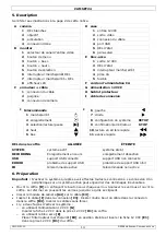
5.
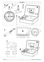
Overview
Refer to the illustrations on page 2 of this manual.
A camera
D case
1
white LEDs
1
12VDC input
2
lens
2
video output
3
spring
3
cable connector
4
gold plated connector
4
USB port
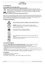
B monitor
5
status indication LEDs
1
video input channel button
6
sunscreen
2
menu button
E battery
pack
3
down button
1
12VDC output
4
up button
2
status indication LEDs
5
select button
3
power on/off switch
6
LED on/off button
4
AC input connector
7
power LED
5
fuse
8
LCD
F AC power cord
C reel + cable
G 12VDC
adaptor
1
cable connector
H protective cap for camera
2
handle
I connection
cable
3
camera connector
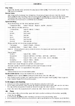
J remote control
J
6
left
1
power on/off
7
right
2
start record
8
system setup
SETUP
3
select/play/pause
9
confirm/stop/return
STOP
4
up
10
fast reverse
5
down
11
fast forward
case LED
ON OFF
SYSTEM
system power on
no power
RECORDING
images are currently being recorded
no recording
USB
USB device connected
no USB device recognized
ERROR
problem detected with USB device
no problems detected
IR
remote control in use
no remote control reception
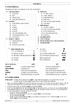
6.
Preparation
Important: only
switch on the power
after
all connections are made. Connecting devices to a live
system will surely cause damage.
•
Open the case
[D]
by pushing on the bottom of the locks until the levers jump out. Then pull up
the levers and lift the top of the case. To close, close the top and push the levers all the way
down.
•
Screw the camera connector
[A4]
on the cable
[C3]
.
•
Connect the cable
[C1]
to the connection cable
[I]
and plug the other end of the connection
cable
[I]
into the case connector
[D3]
. All connectors are slotted and fit only one way.
Do not
force.
•
There are two ways to power the system:
o
via the 12VDC adaptor
[G]
Insert the 12VDC power plug into the 12VDC power input
[D1]
of the case.
o
using the battery pack
[E]


