IG-322-EN version 03; 22/07/2022
21
General instructions
SF
6
-insulated circuit-breaker panel:
Type
gae
.630 -1LSV(G)-/5/
in modular extensible design up to 24 kV, 20 kA
Transport and installation
3.8. Connection of the power cables
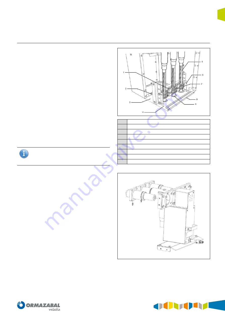
Please proceed as follows to connect the power cables:
• Remove the front cover (see Chapter 5, “Operation”).
• Only on variants with bottom plates: Remove the front
bottom plate and the rubber cable grommets. Push the
rubber cable grommets onto the power cables to be
connected.
• Route the power cables through the floor opening,
cut to length, put in place and mount the male cable
connector or adapter by following the instructions of
the respective manufacturer.
• Only on variants with bottom plates: Insert the power
cables with the rubber cable grommets into the cut-
outs in the rear bottom plate.
• Connect power cables to the panel.
• Fix power cables to the cable fixing iron using the cable
clamps so they are free of strain.
• Connect the earthing cables to the earthing terminals of
the cable fixing iron.
If the circuit-breaker panel is fitted with window-type
current transformers you must route the earthing cable
through the transformer and then to the earthing
terminal of the cable fixing iron.
• Only on variants with bottom plates: Re-fit the front
bottom plate. During this process ensure the rubber
cable grommet is correctly inserted between the
bottom plates.
1
Earthing terminal
2
System earthing
3
Rear bottom plate (optional)
4
Front botto plate (optional)
5
Power cable
6
Cable fixing iron
7
Cable clamp
8
Z-provil
9
Rubber cable gromment
Figure 3.11.
Figure 3.12.
Содержание ORMAZABAL gae.630
Страница 63: ......


