T
wo pumps should empty the vessel when a certain level is reached
.
A
t
80
%
fi
lling
,
the pump with the shortest running time should switch
on
.
I
f the level nevertheless increases
,
a second pump should switch
on at
90
%
.
B
oth pumps should switch o
ff
again at
10
%
fi
lling
.
S
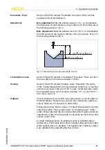
elect in the
DTM
navigation section the menu items
"
M
eas
.
loop
-
O
utputs
-
R
elay
"
.
l
S
et mode
"
P
ump control
2
"
for relay
1
and
2
.
l
E
nter the switching points for the concerned relays as follows
:
-
R
elay
1
upper switching point
=
80
.
0
%
-
R
elay
1
lower switching point
=
10
.
0
%
-
R
elay
2
upper switching point
=
90
.
0
%
-
R
elay
2
lower switching point
=
10
.
0
%
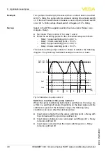
T
he function of the pump control
2
is shown in detail in the following
diagram
.
T
he previously described example is used as a basis
.
Rel. 1: 80% On
On
Off
Off
On
Rel. 2: 90% On
Rel. 1, 2: 10% Off
10
30
20
20
15
t [h]
5
Rel. 1
Rel. 2
F
ig
.
14
:
E
xample of a pump control
2
S
witch on reaction of the pump control
2
W
hen the signal conditioning instrument is switched on
,
the relays are
at
fi
rst in a switched
-
o
ff
status
.
D
epending on the input signal and the
switched
-
on period of the individual relays
,
the following relay
conditions can occur after the start procedure
:
l
I
nput signal is higher than the upper switching point
-
>
R
elay with
the shortest switch on period is switched on
l
I
nput signal is between lower and upper switching point
-
>
R
elay
remains switched o
ff
l
I
nput signal is smaller than the lower switching point
-
>
R
elay
remains switched o
ff
E
xample
S
et up
48
VEGAMET
625
•
D
ouble channel
HART
signal conditioning instrument
8
A
pplication examples
28970
-
EN
-
110801

