TS
d1
h1
h2
d2
1
L2
L1
F
ig
.
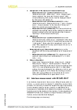
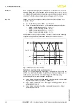
13
:
I
nterface measurement
1
R
eference plane
d
1
D
istance to the interface
,
meas
.
loop
1
d
2
D
istance to the level
,
meas
.
loop
2
TS
T
hickness of the upper medium
(
d
1
-
d
2
),
meas
.
loop
3
(
displayed value
)
h
1
H
eight
-
I
nterface
(
displayed value
)
h
2
H
eight
-
L
evel
(
displayed value
)
L
1
L
ower medium
L
2
U
pper medium
8
.
4
P
ump control
1
/
2
(
running time controlled
)
P
ump control
1
/
2
is used to control several pumps with the same
function dependent on the previous running time
.
A
lways the pump
with the shortest running time is switched on and the pump with the
longest running time switched o
ff
.
W
ith increased requirement
,
all
pumps can also run at the same time dependent on the entered
switching points
.
W
ith this measure
,
a steady utilization of the pumps
is achieved and the reliability increased
.
A
ll relays with activated pump control are not assigned to a certain
switching point but are switched on or o
ff
depending on the operating
time
.
T
he signal conditioning instrument selects the relay with the
shortest operating time when the switch
-
on point is reached and the
relay with the longest operating time when the switch
-
o
ff
point is
reached
.
W
ith this pump control
,
there are two di
ff
erent versions
:
l
P
ump control
1
:
T
he upper switching point determines the switch
-
o
ff
point for the relay
,
whereas the lower switching point
determines the switch
-
on point
l
P
ump control
2
:
T
he upper switching point determines the switch
-
on point for the relay
,
whereas the lower switching point
determines the switch
-
o
ff
point
F
unctional principle
VEGAMET
625
•
D
ouble channel
HART
signal conditioning instrument
47
8
A
pplication examples
28970
-
EN
-
110801


