I
n systems without potential equalisation
,
connect the cable screen
directly to ground potential at the power supply unit and at the sensor
.
I
n the connection box or
T
-
distributor
,
the screen of the short stub to
the sensor must not be connected to ground potential or to another
cable screen
.
T
he cable screens to the power supply unit and to the
next distributor must be connected to each other and also connected
to ground potential via a ceramic capacitor
(
e
.
g
.
1
n
F
,
1500
V
).
L
ow
-
frequency potential equalisation currents are thus suppressed
,
but the
protective e
ff
ect against high frequency interference signals remains
.
T
he total capacitance of the cable and of all capacitors must not exceed
10
n
F
in
E
x applications
.
T
ake note of the corresponding installation regulations for
E
x
applications
.
I
n particular
,
make sure that no potential equalisation
currents
fl
ow over the cable screen
.
I
n case of grounding on both sides
this can be achieved by the use of a capacitor or a separate potential
equalisation
.
5
.
2
C
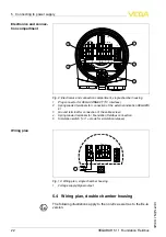
onnection procedure
P
roceed as follows
:
1
U
nscrew the housing cover
2
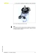
I
f an indicating and adjustment module is installed
,
remove it by
turning it slightly to the left
.
3
L
oosen compression nut of the cable entry
4
R
emove approx
.
10
cm of the cable mantle
,
strip approx
.
1
cm
insulation from the individual wires
5
I
nsert the cable into the sensor through the cable entry
6
L
ift the opening levers of the terminals with a screwdriver
(
see
following illustration
)
7
I
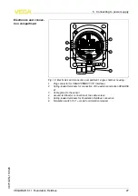
nsert the wire ends into the open terminals according to the wiring
plan
8
P
ress down the opening levers of the terminals
,
you will hear the
terminal spring closing
9
C
heck the hold of the wires in the terminals by lightly pulling on
them
10
C
onnect the screen to the internal ground terminal
,
connect the
outer ground terminal to potential equalisation
11
T
ighten the compression nut of the cable entry
.
T
he seal ring must
completely encircle the cable
12
S
crew the housing cover on
S
ingle
/
D
ouble chamber
housing
VEGABAR
51
•
F
oundation
F
ieldbus
19
5
C
onnecting to power supply
36715
-
EN
-
110629


