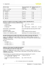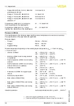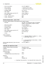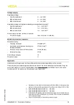
S
hock resistance
A
cceleration
100
g
/
6
ms
16
)
E
lectromechanical data
-
version
IP
66
/
IP
67
C
able entry
/
plug
17
)
-
S
ingle chamber housing
l
1
x cable gland
M
20
x
1
.
5
(
cable
:
ø
5
…
9
mm
),
1
x blind stopper
M
20
x
1
.
5
or
:
l
1
x closing cap
½
NPT
,
1
x blind plug
½
NPT
or
:
l
1
x plug
(
depending on the version
),
1
x blind
stopper
M
20
x
1
.
5
or
:
l
2
x blind stopper
M
20
x
1
,
5
-
D
ouble chamber housing
l
1
x cable entry
M
20
x
1
.
5
(
cable
:
ø
5
…
9
mm
),
1
x blind stopper
M
20
x
1
.
5
;
plug
M
12
x
1
for
the external indicating and adjustment unit
(
optional
)
or
:
l
1
x closing cap
½
NPT
,
1
x blind stopper
½
NPT
,
plug
M
12
x
1
for the external indicating
and adjustment unit
(
optional
)
or
:
l
1
x plug
(
depending on the version
),
1
x blind
stopper
M
20
x
1
.
5
;
plug
M
12
x
1
for the
external indicating and adjustment unit
(
op
-
tional
)
or
:
l
2
x blind stoppers
M
20
x
1
.
5
;
plug
M
12
x
1
for
the external indicating and adjustment unit
(
optional
)
S
pring
-
loaded terminals for wire cross
-
sec
-
tion
<
2
.
5
mm
²
(
AWG
14
)
E
lectromechanical data
-
version
IP
66
/
IP
68
(
1
bar
)
C
able entry
-
S
ingle chamber housing
l
1
x
IP
68
cable gland
M
20
x
1
.
5
;
1
x blind
stopper
M
20
x
1
.
5
or
:
l
1
x closing cap
½
NPT
,
1
x blind plug
½
NPT
C
onnection cable
-
S
tructure
four wires
,
one suspension cable
,
one breather
capillary
,
screen braiding
,
metal foil
,
mantle
16
)
T
ested according to
EN
60068
-
2
-
27
.
17
)
D
epending on the version
M
12
x
1
,
according to
ISO
4400
,
H
arting
,
7
/
8
"
FF
.
VEGABAR
51
•
F
oundation
F
ieldbus
59
10
S
upplement
36715
-
EN
-
110629


