T
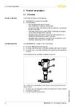
he process pressure acts on the sensor element via the stainless
steel diaphragm
.
T
he process pressure causes a resistance change
which is converted into a corresponding output signal and outputted as
measured value
.
1
)
P
ower is supplied via the
H
1
F
ieldbus
.
A
two
-
wire cable according to
F
ieldbus speci
fi
cation serves as carrier of both power and digital data
for multiple sensors
.
T
his cable can be operated in two versions
:
l
via an
H
1
interface card in the control system and additional power
supply
l
via a
L
inking device with
HSE
(
H
igh speed
E
thernet
)
and
additional power supply according to
IEC
61158
-
2
T
he
DD
(
D
evice
D
escriptions
)
and
CFF
(
capability
fi
les
)
necessary for
planning and con
fi
guration of your
FF
(
F
oundation
F
ieldbus
)
commu
-
nication network are available in the download area of the
VEGA
homepage www
.
vega
.
com under
"
S
ervices
-
D
ownloads
-
S
oftware
-
F
oundation
F
ieldbus
"
.
T
he appropriate certi
fi
cates are also available
there
.
A CD
with the appropriate
fi
les and certi
fi
cates can be ordered
via e
-
mail under info
@
de
.
vega
.
com or by phone from one of the
VEGA
agencies under the order number
"
DRIVER
.
S
"
.
T
he backlight of the indicating and adjustment module is powered by
the sensor
.
P
rerequisite is a certain level of operating voltage
.
T
he data for power supply are speci
fi
ed in chapter
"
T
echnical data
"
.
T
he optional heating requires its own operating voltage
.
Y
ou can
fi
nd
details in the supplementary instructions manual
"
H
eating for indicat
-
ing and adjustment module
"
.
T
his function is generally not available for approved instruments
.
3
.
3
C
on
fi
guration
T
he instrument can be adjusted with the following adjustment media
:
l
with indicating and adjustment module
l
with the suitable
VEGA DTM
in conjunction with an adjustment
software according to the
FDT
/
DTM
standard
,
e
.
g
.
PACT
ware and
PC
l
a con
fi
guration tool
3
.
4
P
ackaging
,
transport and storage
T
he device was protected by packaging during transport
.
I
ts capacity
to handle normal loads during transport is assured by a test according
to
DIN EN
24180
.
1
)
M
easuring ranges up to
16
bar
:
piezoresistive sensor element with internal
transmission liquid
.
M
easuring ranges up to
25
bar
:
strain gauge
(
DMS
)
sensor element on the rear of the stainless steel diaphragm
(
dry
).
F
unctional principle
P
ower supply and bus
communication
DD
/
CFF
P
ackaging
10
VEGABAR
51
•
F
oundation
F
ieldbus
3
P
roduct description
36715
-
EN
-
110629


