File Prefix:
String of alphanumeric characters to be appended at the beginning of the file name, every time the results are saved. For
example Fiber0239-
Starting #:
Every time a result is saved, this suffix number will automatically increment. Users can manually enter the initial value
here.
Auto Freeze:
This is amount of time the optional Auto Focus Detection feature will look for a stable in-focus image before
automatically freezing the image and starting an analysis. Select Never, if manual capture or real-time analysis is desired. Auto freeze
comes handy when both hands are tied (e.g. one holding the connector and the other holding the probe, or working on a pole)
Scope Mode:
Use Local for USB fiber inspection scopes that directly attached to the test set. Use Remote if the probe is attached to
a wireless transmitter using Wi-Fi connection.
7.4.1.7 Capture Tab (View)
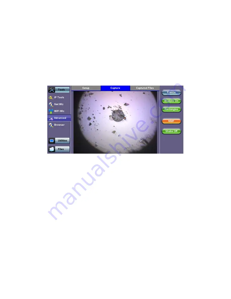
The Capture tab is the main user interface for the connectors’ face inspection and analysis. It presents a real-time view of the
connector’s end face allowing users to align and focus.
Fiber Scope - Capture tab
Important!
The soft buttons in the action bar (right side of the screen) do not indicate the current state or setting, they indicate the
action that would take place if pressed. For example, if user taps on the “Analysis OFF” button, the analysis function is turned OFF
and the button toggles to show “Analysis ON”. These soft buttons should be interpreted as “Go to…”
Freeze:
Allows users to manually freeze the image in the desired view. If the optional Auto Focus Detection feature is enabled, the
test set will automatically freeze the image when the image comes into focus. Once the image is frozen, users can tap on the image
to save it.
Analysis ON/OFF:
Turns the optional auto-analysis feature ON and OFF. If turned ON, the test set automatically analyzed the image
in real time. If the markers get in the way of seeing the picture details, users can turn this feature OFF and perform manual analysis.
Dots/Rectangles:
They are two ways of highlighting the different impurities found in the face of the connector. The dots tightly contour
each individual anomaly, capturing its area. In some cases users may want to see impurities or scratches that are otherwise covered
by the dots, so rectangles are used in this case to highlight the anomaly and still keep them visible. The selection between dots or
rectangles does not affect the area calculation r the Pass/Fail results; they are just operator’s choice.
Save:
The Save button appears after freezing an image. I performs the same action as tapping on the screen to save the current
image. Use the >Utilities >Files function to View the report, export to PDF format and copy to USB.
MTTplus e_Manual D07-00-096P RevA00
Page 49 of 66
Содержание MTTplus
Страница 1: ...MTTplus e_Manual D07 00 096P RevA00 Page 1 of 66...
Страница 7: ...3 1 MTTplus Overview Side View Go back to TOC MTTplus e_Manual D07 00 096P RevA00 Page 7 of 66...
Страница 21: ...Web Browser Password Prompt MTTplus e_Manual D07 00 096P RevA00 Page 21 of 66...
Страница 40: ...Go back to TOC MTTplus e_Manual D07 00 096P RevA00 Page 40 of 66...
Страница 46: ...Go back to TOC MTTplus e_Manual D07 00 096P RevA00 Page 46 of 66...


