6-1
6
Checking the System
Setting the Signal Strength Jumper
IMPORTANT! You must install the WPLLD transducer prior to performing this procedure.
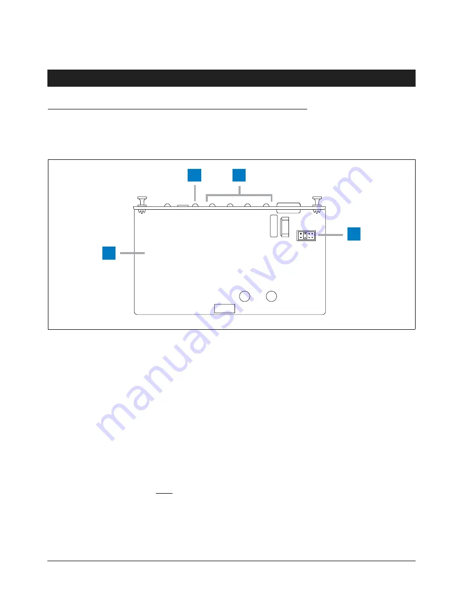
To obtain optimum signal reception from the transducer, it may be necessary to change the noise/signal strength jumper
position (see Figure 6-1). The default position is R98.
Figure 6-1. Noise/Signal Strength Jumper Settings
GUIDELINES
1. For optimum data reception, the LEDs on the front of the WPLLD AC Interface Module should turn On as follows.
a. When a WPLLD transducer is not transmitting:
None of the 4 red LEDs should be lit (indicating no noise on the line). One dimly flashing red LED is acceptable;
however, if more than 1 of the red LEDs are flashing, you have excessive noise on the ac line and it should be
removed before continuing. Start turning off electrical signs, motors, etc., one item at a time, until the noise is
eliminated. Replace the device causing the noisy condition.
R101 R98 R96 R93
wplld/acunder.eps
1
2
3
4
Legend for numbered boxes in Figure 6-1:
1
Underside of WPLLD AC Interface Module.
2
Green XMIT LED - flashes when information is received from a WPLLD transducer.
3
Number of LEDs lit indicate signal strength received from WPLLD transducers. At least 3 LEDs
should be lit, when receiving transducer communications, indicating good signal strength.
4
Noise/signal strength jumper settings. R98 is default setting.


