Table of Contents
iii
Figures
Figure 1.
Control Drawing - Example TLS-HLD System Site Layout .......................3
Recommended Mounting of Console .........................................................7
Console Dimensions and Designated Conduit Knockouts ........................8
Wiring AC Power to the Console ...............................................................9
Installing Probe Canister Spacer Rings ...................................................11
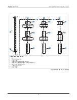
Probe Float/Boot Installation ...................................................................12
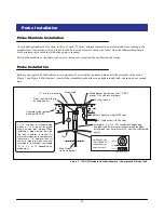
TLS-HLD Probe Installation Example - Underground Storage Tank........13
TLS-HLD Probe Installation Example - Above ground Storage Tank .....14
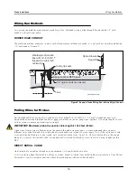
Example Probe Wiring Run in Buried Rigid Conduit ...............................15
Example Probe Wiring Run Via Direct Burial Cable ................................16
Probe Field Wiring Connection ................................................................17
Epoxy Sealing Connections ....................................................................18
Probe Installation Directory .....................................................................19
Connecting Probe Wiring to Console ......................................................20
Console Connected to a Remote Device Via Short-Haul Modem ...........23
Console Dip Switch Settings ...................................................................24
DB9, RS-232 Pin-Outs ............................................................................ 25
CPU Board Voltage Test Points ..............................................................49
Removing PROM Chip ............................................................................51
Replacing PROM Chip ............................................................................52


