Probe Installation
Probe Conduit Installation
14
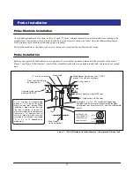
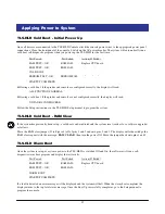
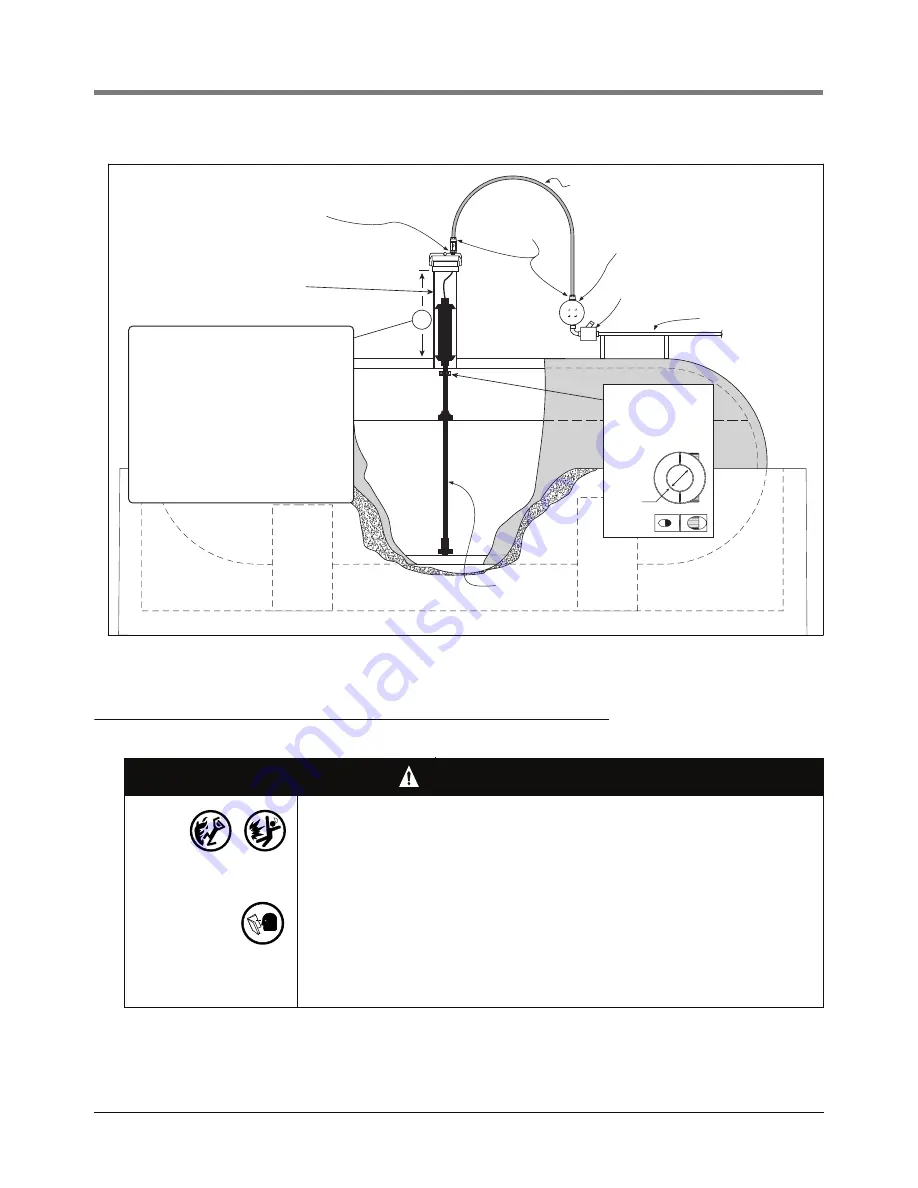
Figure 8. TLS-HLD Probe Installation Example - Above ground Storage Tank
Probe Conduit Installation
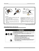
WARNING
Probes operate in areas where flammable liquids and explosive vapors may be
present.
Improper installation may result in fire or explosion causing serious injury or
death.
Practice the following:
1. Read thoroughly and follow the instructions shipped with each probe.
2. Probe wiring conduit must not contain any other wires.
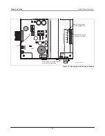
3. Probe wiring and conduits must enter the console only through their
designated areas (see Figure 3).
4. Power and communication wires and conduit must not enter the
intrinsically safe compartment of the console. (see Figure 3).
Use bushing and body of grip
fitting supplied with probe and
Adaptor nut supplied with
AST kit.
Epoxy seal per NFPA specs
Flexible metal conduit
supplied with AST kit
Weatherproof junction box with
1/2" NPT threads (16 cubic inch
minimum)
Rigid conduit
Liquidtight
fittings from
AST kit
Mag Probe
(rests on bottom)
probes\astpbins.eps
Riser pipe - 2, 3, or 4'' API
schedule 40 - depending on
probe type
A
A = 18" minimum for standard mag
probes or 14" minimum for global
mag plus/mag plus probes. When
installing a probe longer than the
the tank diameter, increase this
minimum dimension to compensate.
(Example: a 7'-6'' diameter tank will
use an 8' probe, in which case you
must add 6" to minimum riser length
'A', i.e., 24" or 18" depending on
probe type).
Split-Ring Collar
(P/N 576008-617)
required if probe
enters the riser.
Top view
Side view
3/4" ID


