7
Console Installation
Mounting the Console
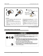
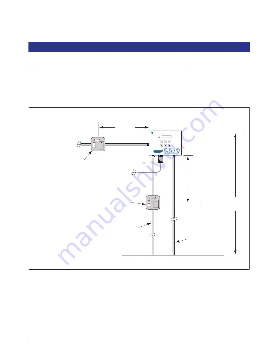
Figure 2 illustrates recommended console mounting. Install the console fastening devices to the mounting surface using
the hole pattern (6.7” x 5.7”) shown in Figure 3. Mounting screws up to 3/16” diameter may be used.
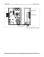
Install metal conduit (1/2” I.P.S.) between the console and the power panel. Figure 3 shows the three designated
knockouts (one each on top, left side, and bottom) through which power wiring can safely enter the console.
Figure 2. Recommended Mounting of Console
consoles\hldmnt.eps
1500 mm
(Maximum)
1000 mm
(Maximum)
1000 mm
(Maximum)
One 5 ampere fused, switched, neon
indication spur (for 240 Vac), or a dedicated
circuit breaker rated for 15 amperes, 120 Vac
or 240 Vac. NOTE, circuit breaker must be
marked as the power disconnect for the console.
From an independent 24 hour supply at the distribution
panel, run three 2.5 mm (minimum) standard color coded
wires; live, neutral, and earth, to the fused spur. Run one
4 mm wire, color coded green/yellow, from the earth bus
bar at the distribution panel direct to the console location.
Leave at least 1 metre of free cable for connection to the
console.
To an external alarm (i.e., Forecourt Alarm)-
One 2 ampere fused, switched, neon indication
spur or a dedicated circuit breaker rated
for 120 Vac or 240 Vac. NOTE, circuit breaker
must be marked as the external alarm
disconnect for the console.
Communication
cable
Conduit for probe
field cables
VEEDER-ROOT
Height Level Display
TLS


