background image

  Setup

Introduction

This section describes how to perform PMC setup using the TLS console’s front panel buttons and display. The 
procedures in this manual follow standard TLS console setup programming input, i.e., keypad/display interaction. If 
necessary, refer to Section 2 of the TLS-3XX System Setup manual (P/N 576013-623) to review entering data via 
the front panel keypads.

All PMC-related equipment must be installed in the site and connected to the TLS console prior to beginning the 
setups covered in this section. As with all TLS connections, you cannot change sensor wiring or module slots after 
programming or the console may not operate properly. Reference the section entitled “Connecting Probe/Sensor 
Wiring to Consoles” in the TLS-3XX Site Prep and Installation manual (P/N 576013-879) for rewiring precautions.

Smart Sensor Setup

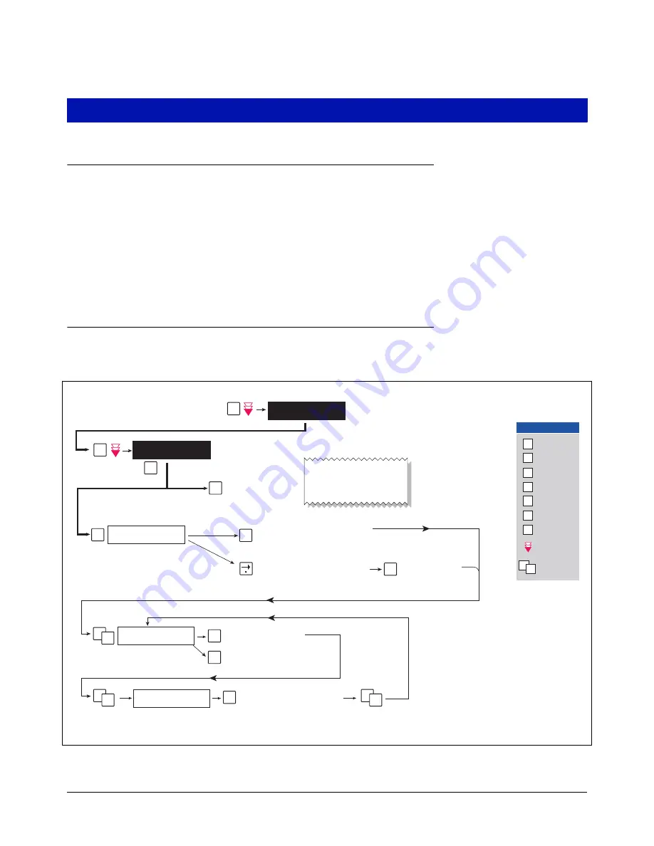
The Smart Sensor Interface Module is installed in the Intrinsically-Safe bay of the TLS console. This module 
monitors the Vapor Pressure Sensor. Figure 2 diagrams the Smart Sensor setup procedure.

Figure 2.  Smart Sensor Setup

SS CONFIG - MODULE  1
SLOT X - X  X  X  X  X  X  X  X

S

isd\pmc-5.eps

ENTER SMARTSENSOR LABEL
sX:

S1: SELECT SS CATEGORY
UNKNOWN

C

C

E

S

E

S

E

S

P

F

SMARTSENSOR SETUP
PRESS <STEP> TO CONTINUE

SETUP MODE

PRESS <FUNCTION> TO CONT

M

P


C

C

C

F

P

S

T

Change

E

Enter

Function

Print

M

Mode

Step

Tank/Sensor

Key press
sequence

Repress until
desired message
appears in display

Key Legend

1

2

Select sensor category
(e.g., Vapor Pressure Sensor)

Press this button and select type. 
Note: User can only change assigment 
if device has not identified itself. If 
actual device disagrees with assigned 
type, actual type overrides assigned 
type.

The first of the installed SS modules 
appears in this display. If this is not the 
module to which the Vapor Pressure 
Sensor (VPS) is connected, press the 
Tank/Sensor button to select another 
SS module. 

Press once and the first position blinks. If 
the VPS is connected to the first position 
of the SS module, press this button again 
and the X changes to a 1.

Press this button and 
the X changes to the 
number of the VPS 
connection (2-8).

Prints out a copy of the 
SmartSensor Setup.
See example at right.

Press this button and enter 
a label for the sensor, e.g., 
VPS: FP1&2.

T

Press this button to 
change to another sensor.

If the VPS is connected to a position other 
than the first, continue to press this button 
until the VPS connected position blinks.

SMARTSENSOR SETUP

---------------------- 

S01:VP SENSOR

CATEGORY VAPOR PRESSURE

Section 16

Pressure Management Control

16-5

Содержание TLS-350R

Страница 1: ...Manual No 577013 801 Revision A Install Setup Operation Manual Pressure Management Control Section 16 Pressure Management Control 16 i...

Страница 2: ...tailed description of the damage on the face of the freight bill The carrier s agent must verify the inspection and sign the description 2 Immediately notify the delivering carrier of damage or loss T...

Страница 3: ...a period of one 1 year from the date of installation or twenty four 24 months from the date of invoice whichever occurs first During the first ninety 90 days we or our representative will repair or re...

Страница 4: ...and Runtime Fault Alarm 19 Manual control 19 PMC Diagnostic Menu 19 Figures Figure 1 TLS console Interface Module Bays 3 Figure 2 Smart Sensor Setup 5 Figure 3 PMC Setup 6 Figure 4 TLS console alarm...

Страница 5: ...Port will be available for use by contractor or government inspectors Contractor Certification Requirements Veeder Root requires the following minimum training certifications for contractors who will...

Страница 6: ...is sup plied to the device A potential shock hazard exists TURN POWER OFF Live power to a device creates a potential shock hazard Turn Off power to the device and associ ated accessories when servicin...

Страница 7: ...which interface modules can be installed Comm bay Power bay and Intrinsically Safe bay ref Figure 1 Probe Interface modules and Smart Sensor modules are installed in the Intrinsically Safe bay and the...

Страница 8: ...em Grounding Probe and Sensor Shields Connect probe and sensor cable shields to ground at the console only Do not ground both ends of the shield CIRCUIT DIRECTORY A circuit directory is adhered to the...

Страница 9: ...ECT SS CATEGORY UNKNOWN C C E S E S E S P F SMARTSENSOR SETUP PRESS STEP TO CONTINUE SETUP MODE PRESS FUNCTION TO CONT M P C C C F P S T Change E Enter Function Print M Mode Step Tank Sensor Key press...

Страница 10: ...tes after start time Data collected 5 minutes before the Start of Test time is omitted from test S SET ANALYSIS TIME PRESS ENTER E S SET TEST START TIME TIME hh mm SET POST DELAY DURATION DELAY MINUTE...

Страница 11: ...rm messages The system automatically prints an alarm report showing the alarm type its location and the date and time the alarm condition occurred Warning and alarm posting causes the TLS console base...

Страница 12: ...ime the alarm was posted Alarm example in Figure 6 PMC Alarms are logged into the Priority Alarm History in the TLS Figure 6 TLS console alarm example MMM DD YYYY HH MM XM VP EMISSIONS WARN PMC ALARM...

Страница 13: ...VST ASC Level C Warnonthefirst day Yellow VP EMISSIONS To notify when the mass emissions exceeds the defined threshold for the system Failonconsecutive days Red TLS 350PMCVariablesetup ConfirmationPr...

Страница 14: ...YY HH MM SS XM ALL FUNCTIONS NORMAL S S S S EFFLUENT EMISSIONS TEST STATUS PASS S VP DUTY CYCLE TEST STATUS PASS pmc fig7 eps Prints out a copy of the PMC Status report See example at right C F P S T...

Страница 15: ...S 232 board DB25 female Slots 1 2 or 3 ATEN USB to DB9 serial adapter P N 576040 170 Serial I O PC Card Plugs into PCMCIA port Multiport board DB9 female Slot 4 Laptop TLS 350R TLS 350R USB male lapto...

Страница 16: ...tton you may see a repeat of the modem dialing windows in which case ignore cancel them all 4 When the Connect To window appears Figure 10 depending on your connection method select either COM1 If RS...

Страница 17: ...disabled If the code was enabled you would see a 6 digit number which you will need to enter to access the console refer to the Sending Console Commands paragraph below for more information SETUP MOD...

Страница 18: ...o the main screen If the RS 232 Security Code is disabled press and hold the Ctrl key while you press the A key then type in IV8200 If the RS 232 Security Code is enabled e g 000016 you must enter the...

Страница 19: ...ocessor Status Report See example Figure 13 SOH IV8200 Vapor Processor Runtime Diagnostic Report See example Figure 14 SOH IV8000 Percent Hydrocarbon Diagnostic Report See example Figure 15 SOH IV8100...

Страница 20: ...SSOR PMC MONITORING TEST PASS FAIL THRESHOLDS PERIOD BELOW ABOVE VAPOR PROCESSOR PRESSURE FAIL 90th PERCENTILE 1DAYS 1 00 INCHES H2O VAPOR PROCESSOR MASS EMISSION FAIL 1DAYS 0 64 LBS 1KG VAPOR PROCESS...

Страница 21: ...5 NO 3 09 07 1 15PM 17 92 0 278 0 268 NO 3 10 07 3 01AM 7 70 0 200 0 223 NO 3 10 07 4 30AM 4 02 0 202 0 224 NO 3 10 07 7 54PM 23 62 0 306 0 245 NO 3 11 07 11 24PM 6 55 0 256 0 213 NO 3 12 07 11 31PM 2...

Страница 22: ...M 1 042 8 25 07 7 57AM 1 040 8 25 07 7 57AM 1 040 8 25 07 7 57AM 1 032 8 25 07 7 57AM 1 030 8 25 07 7 56AM 1 050 8 25 07 7 56AM 1 040 8 25 07 7 56AM 1 040 8 25 07 7 56AM 1 032 8 25 07 7 55AM 1 050 8 2...

Страница 23: ...anual Note If the PMD is on and the PMC mode is Automatic changing the control mode to Manual mode will turn the PMD off PMC Diagnostic Menu Figure 16 PMC Diagnostic Menus PMC VERSION 01 00 PRESS STEP...

Страница 24: ...For technical support sales or other assistance please visit www veeder com Section 16 Pressure Management Control 16 20...

Отзывы: