IQ Control Box Installation and Owner’s Manual
Setup Switch Chart
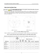
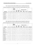
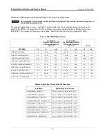
15
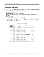
10. The unit must be calibrated every time the Motor Type programming is performed even if the Motor Type does
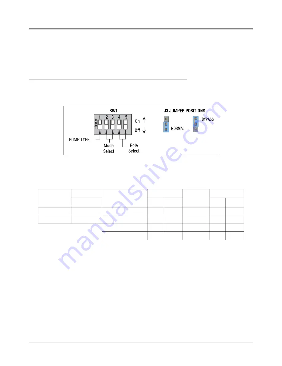
not change. Set the five DIP switches to the desired pump type and mode / role select configuration (see
Figure 11). NOTE: The unit will not calibrate if a Motor Type has not been programmed.
Setup Switch Chart
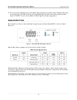
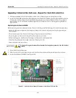
Each controller must have its duty established through the dip switch bank labeled SW1 on the circuit board
(Figure 11).
Figure 11. Dip Switch SW1 and Bypass Jumper J3
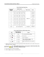
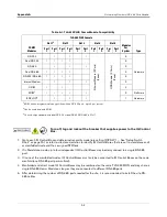
Follow Table 7 below to properly set the five switches for the controller.
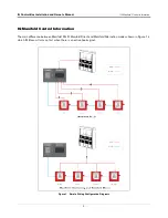
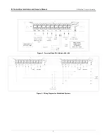
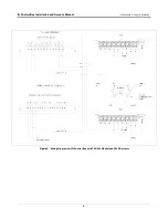
Manifolded PLLD mode allows interfacing with an ATG console. This mode has special communication wiring
requirements. Refer to Figure 5 for IQ Control Box with manifolded PLLD systems or Figure 6 for IQ Control Box
with manifolded DPLLD systems
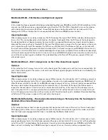
Manifolded Direct mode allows for a primary pump to initiate all dispensing events and secondary pumps to help
when required. The control box set as Unit 1 (switch 4 & 5 on) is the Primary.
Table 7. Motor Type Selections
Pump Type
Switch
Mode Select
Switch
Role
Select
Switch
1
2
3
4
5
Standard
ON
Stand Alone
ON
ON
Unit 1
ON
ON
X-Series
OFF
Manifolded PLLD
ON
OFF
Unit 2
ON
OFF
Manifolded Alternating
OFF
ON
Unit 3
OFF
ON
Manifolded Direct
OFF
OFF
Unit 4
OFF
OFF

