Appendix A
Installing RS-485 Wiring Between IQ Control Boxes & TLS-450PLUS
A-3
Installing RS-485 Wiring Between IQ Control Boxes & TLS-450PLUS
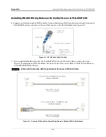
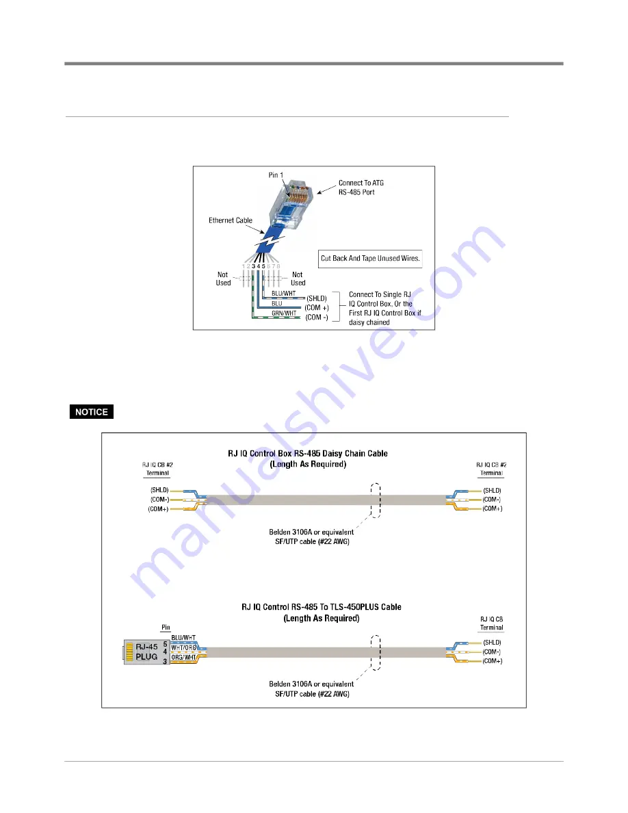
6. Prepare a satisfactory length of CAT5 or better 3-wire cable having a RJ-45 connector on one end (connects to
TLS-450PLUS and no connector on the end that connects to the IQ Control Box (see Figure A-1).
Figure A-1. RS-485 Serial Cable Pin-Outs
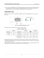
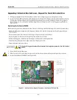
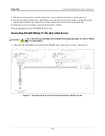
7. Run completed RS-485 cables from the TLS-450PLUS to the first IQ Control Box in a daisy chain (see
Figure A-2) and between IQ Control Boxes, but do not connect the comm cables to the IQ Control Boxes or
to the TLS-450PLUS at this time.
Lable each Comm wire with its polarity and the source IQ Control Box.
Figure A-2. Example IQ Control Box Comm Wiring Example (Belden 3106A Cable Shown)

