background image

Transformer Ration Analysis Software Manual 


15


4.2.1 Delete Test Record or Test Plan Menu 

The delete function removes a test plan or test record from the directory to which the program is 
pointing. Care must be used with this function as it is permanent and deleted files cannot be recovered. 

The deleted files are not sent to the Windows 

TM  

Recycle Bin.  


Select the “Delete” sub option from the “Utilities” menu and then select the type of file to be deleted 
(Figure 8). Select the file to be deleted from the directory window and click the “OK” button. The file 
will be permanently removed.  
 

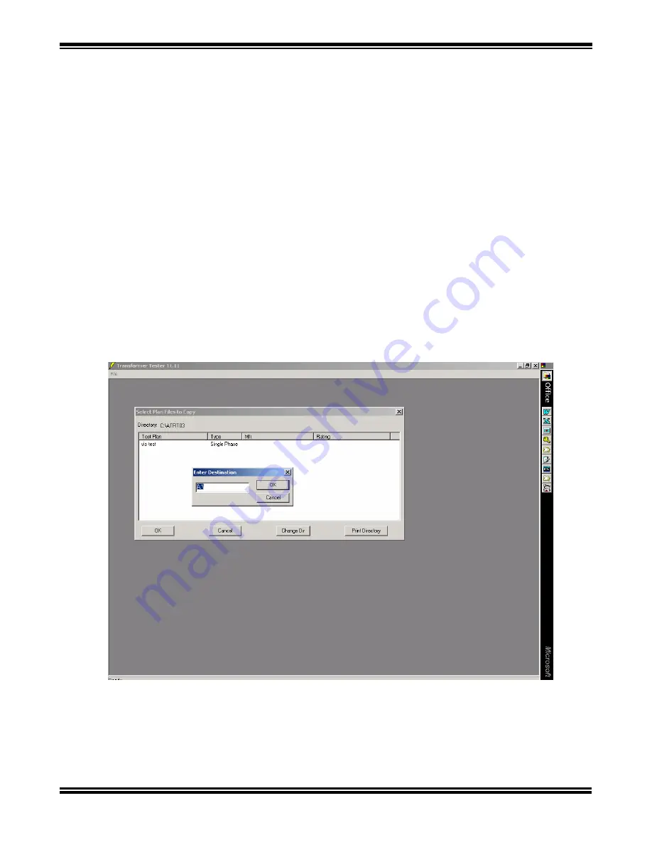
4.2.2 Copy Test Record or Test Plan Menu 

The copy function permits the copying of a test record or test plan stored on the PC to any destination 
that is available to the PC. This can range from another folder on the same drive, to a floppy disk, 
Flash drive, or a network drive.  This function allows users to share test plans and test records.  
 
Select the “Copy” sub option from the “Utilities” menu and then select the type of file to be copied 
(Figure 8). Select the file to be copied from the directory window and click the “OK” button. A 
dialogue box asking for the destination will appear as shown in Figure 1.  Type in the path to the 
destination and click the “OK” button of the dialogue box (default destination is A drive). The file will 
be copied to the destination and both the directory window and the dialogue box will be closed. 


Figure 11.  Copy a Test Plan Menu 


Содержание ATRT-03

Страница 1: ...he Transformer Ratio Analysis Software Models ATRT 03 ATRT 03A and ATRT 03B Transformer Turns Ratio Meters Vanguard Instruments Co Inc 1710 Grevillea Court Ontario California 91761 TEL 909 923 9390 Oct 2005 FAX 909 923 9391 REV 04 ...

Страница 2: ... Floppy or Drive 16 4 2 4 Export a Test Record or Test Plan 18 5 0 EXCHANGING INFORMATION WITH THE ATRT 03 18 5 1 Retrieving Test Records From the ATRT 03 18 5 2 Retrieving Test Plans From ATRT 03 Memory 20 5 3 Transfer a Test Plan To The ATRT 03 21 6 0 CREATING A TEST PLAN 23 6 1 Creating a Test Plan For a Transformer 23 6 2 Create a Test Plan for a Load Tap Changer 29 6 3 Create a Test Plan for ...

Страница 3: ...4 Figure 20 Create a Transformer Test Plan Menu 3 25 Figure 21 Create a Transformer Test Plan Menu 4 26 Figure 22 Create a Transformer Test Plan Menu 5 27 Figure 23 Create a Transformer Test Plan Menu 6 28 Figure 24 Create a Test Plan For Load Tap Changer Menu 1 29 Figure 25 Create a Test Plan for a Load Tap Changer Menu 2 31 Figure 26 Create a Test Plan for Voltage Regulator 32 Figure 27 Recalled...

Страница 4: ...rmal printers can be obtained with the ATRT 03 and ATRT 03A The program allows the users to run transformer turns ratio test directly from a PC using the ATRT 03 under computer control mode Since test results are sent electronically to the PC no manual transfer of data is required thus eliminating human error in the data collection process Running a test using a test plan from the PC the test resu...

Страница 5: ... hard drive space Windows 95 or later version RS 232 COM port 1 2 RS 232C Cable The ATRT 03 Software Package is shipped with a four 4 foot long RS 232 cable The cable is a serial communications extension cable that uses male to female 9 pin D type connectors The pin connections are as follows Male Female Signal 2 2 Tx 3 3 Rx 5 5 Gnd NOTE A null modem cable which crosses pins 2 and 3 will not work ...

Страница 6: ...puters will automatically access the CD drive and a window will appear showing its contents If not the disk s contents can be accessed by using the Windows Explorer or My Computer icons on the desktop 2 The ATRT setup revxx xx exe file on the disk can be run from a copy made to an appropriate folder on the PC s hard drive or the setup file can be run from the disk 3 Click on Next to complete insta...

Страница 7: ...alysis Software Manual 7 4 When the installation is complete the screen shown in Figure 2 0 will display It is recommended that the shortcut be copied or moved to the desktop for quick access Figure 2 Software Setup Menu 2 ...

Страница 8: ... ATRT 03 to operate Many of its functions only require a computer To start the program on the PC double click the Transformer Tester icon shown in Figure 2 on the desktop or the attr exe file 3 1 Program Main Screen Once the program has started the main screen shown in Figure 3 will display Figure 3 Program Main Screen ...

Страница 9: ...he File button to see the drop down menu see Figure 4 The options with right facing arrows have sub options that are also available Clicking on one of these options will list its sub options Clicking on the sub option will select it Figure 4 Main Menu Bar ...

Страница 10: ...performed especially when the program is being used for the first time on a particular PC or when the printer or communications port being used has changed Selecting the Printer Setup menu option will display the standard Windows TM Printer Setup dialogue box as shown in Figure 5 Select the printer to be used and the appropriate options with the dialogue box Figure 5 Print Setup Menu ...

Страница 11: ... port to be used from the port list Test limit defines the number of tests to be used in the transformer test plan If the transformer has 10 tap positions the test limit should be set to 10 Type the maximum number of tests that need to be run in the Test Limit box Clicking the Save Setup File will use these selections as default values when the program is run again Figure 6 Program Setup menu ...

Страница 12: ...r option of the File menu It displays the calculator dialog box shown in Figure 7 To use the calculator type in the H voltage X voltage and select transformer type Click on the Calculator button to get the ratio The percent option allow the user to calculate turn ratio at a percentage based on the name plate voltages Figure 7 Calculator Menu NOTE The above figure shows H name plate voltage of 12 0...

Страница 13: ...unctions is selected The directory window only shows the type of files that were selected in the second level sub option If test plans were selected then only PLN files will be displayed If tests were selected then only tst files will be displayed Test plan files are selected in Figure 8 above To select a file displayed in the window click on the file to highlight it then click the OK button Click...

Страница 14: ...ow of Test Plan Menu The user can also print the directory by clicking the Print Directory button The Windows TM Printer Setup dialogue box appears and is defaulted to the printer selected in Section 3 2 This is shown in Figure 10 Figure 10 Print Test Plan Directory Menu ...

Страница 15: ... Menu The copy function permits the copying of a test record or test plan stored on the PC to any destination that is available to the PC This can range from another folder on the same drive to a floppy disk Flash drive or a network drive This function allows users to share test plans and test records Select the Copy sub option from the Utilities menu and then select the type of file to be copied ...

Страница 16: ...ther source or location to the folder to the working folder Select the Copy From Floppy sub option from the File menu Figure 8 A dialogue box asking for the path of the source files to be copied will appear as shown in Figure 12 The default path is set for A drive The user can type in the path to the source and click the OK button of the dialogue box Figure 12 Copy a Test Plan From a Directory Men...

Страница 17: ...pear with a list of files to be selected Select the files to be copied Click the OK button of the directory window and the file will be copied to the folder to which the program is pointing and the directory window will be closed Figure 13 a Test Plan From a Directory Menu 2 ...

Страница 18: ...t the ATRT 03 under computer interface perform the following steps 1 Use the provided RS232 cable to connect the ATRT 03 to the PC 2 Put the ATRT 03 into computer interface press key 2 SETUP press key 4 NEXT PAGE press key 1 COMP ITF The order in which the previous steps are performed is not important It is only necessary that the steps be completed Failure to complete any step will result in a co...

Страница 19: ...est Record Directory menu will disappear after the file transfer is completed The test record file name uses the file name prefix and the test plan number listed in the directory For example select test record 1 from the ATRT 03 memory the file name shall be TEST1 The Filename Prefix box allows the user to type in text that will precede the test record number The default file name prefix is TEST A...

Страница 20: ... Select All button in the dialogue box Figure 15 ATRT 03 Test Plan Directory Click the OK button to retrieve the selected test plans from the ATRT 03 memory now The program will retrieve the test plans from the ATRT 03 and store in the working directory The Test Plan Directory screen will disappear after the file transfer is completed The test plan file name uses the file name prefix and the test ...

Страница 21: ...16 Note Only one test plan can be transferred to the ATRT 03 at a time Figure 16 Test plan Directory Display Clicking the Change Directory button will change the path to the directory which contains the test plans This brings up the Browse Folder dialogue box also shown in Figure 18 To select a folder click on it to highlight it then click the OK button Any test plan files in the selected director...

Страница 22: ...cation 1 to 128 in the ATRT 03 memory then click OK button The ATRT 03 will audibly beep several times during the data transfer The directory screen will disappear when downloading has finished Figure 17 ATRT 03 Test Plan Memory Directory The user can also print the directory by clicking the Print Directory button The Windows TM Printer Setup dialogue box appears and is defaulted to the printer se...

Страница 23: ...voltages listed on the nameplate of the units to be tested The program will automatically create a calculated turns atio table based on the input parameters 6 1 Creating a Test Plan For a Transformer To create a test plan for a transformer click the Create Test Plan option from the File menu Select the Transformer sub option see Figure 18 and the empty test plan shown in Figure 19 will appear Figu...

Страница 24: ...cell Begin entering the H voltage H Tap X voltage X Tap from the transformer faceplate information Use the Tab key to move from cell to cell horizontally Use the Up and Down arrow key to move from cell to cell vertically The user can also move to any cell by pointing the arrow to the cell then click on the mouse When any row s H and X voltages have been entered the corresponding Calc Ratio value w...

Страница 25: ...cells or eliminate extra cells for the test plan being generated Figure 20 The default number in the Number of Tests text box is the value entered as the test limit in the program setup see Section 3 2 This number will determine the number of rows the blank test plan will have Figure 20 Create a Transformer Test Plan Menu 3 ...

Страница 26: ...ave As options in the File menu see Figure 21 Figure 21 Create a Transformer Test Plan Menu 4 The Windows TM file save dialogue box appears as shown in Figure 22 Select the proper directory where the test plan is to be stored and enter the name to be given the test plan Click the Save button to complete the save operation ...

Страница 27: ... Test Plan Menu 5 The name of the test plan will now appear in the top status bar of the window see Figure 23 Close the window by selecting the Close option from the main menu refer to Figure 8 The test plan is now stored in the PC s memory and ready to be recalled to run a test ...

Страница 28: ...Transformer Ration Analysis Software Manual 28 Figure 23 Create a Transformer Test Plan Menu 6 ...

Страница 29: ... Load Tap Changer To create a test plan for a load tap changer click the Create Test Plan option from the File menu Select the Load Tap Changer sub option see Figure 18 and the dialogue box shown in Figure 24 will appear Figure 24 Create a Test Plan For Load Tap Changer Menu 1 ...

Страница 30: ... on the high side of the transformer Extra Tests This is to add extra tests other than the ones automatically generated by the program An extra row will be added for each extra test in the test plan Once all the values have been entered click the OK button and a test plan similar to that shown in Figure 25 will appear Notice the extra rows for each extra test Enter the header information The user ...

Страница 31: ...Transformer Ration Analysis Software Manual 31 Figure 25 Create a Test Plan for a Load Tap Changer Menu 2 ...

Страница 32: ... a Voltage Regulator To create a test plan for a load tap changer click the Create Test Plan option from the File menu Select the Load Tap Changer sub option see Figure 18 and the dialogue box shown in Figure 26 will appear Figure 26 Create a Test Plan for Voltage Regulator ...

Страница 33: ...oltage at neutral Tap Location Low taps are on low side of the transformer High taps are on the high side of the transformer Once all the values have been entered click the OK button and a test plan similar to Figure 25 will appear Enter the header information The user can use the PC TAB key to move from one text box to the next or use the mouse pointer to click in the desired text box With the mo...

Страница 34: ...ck OK and the test plan will appear on the screen as show below Figure 27 Recalled Test Plan Although editing of test plans is permitted only certain parts of the test plan can be changed Transformer test plans allowing editing of the header information and values in the H Voltage H Tap X Voltage and X Tap columns Load tap changer and voltage regulator test plans only allow the header information ...

Страница 35: ...tory button will change the path to the directory which contains the test plans This brings up the Browse Folder dialogue box shown in Figure 16 To select a folder click on it to highlight it then click the OK button Any test plan files in the selected directory will be displayed in the directory window and the directory path will be updated When the desired folder has been highlighted click the O...

Страница 36: ...lick OK and the test plan will appear on the screen as shown in Figure 29 The Phase and Calc Ratio columns will be automatically calculated and filled in Header information may be added or changed to identify the test to be run Figure 29 Run a Transformer Test Using a Test Plan Step 2 ...

Страница 37: ...T 03 for instructions on connecting the ATRT 03 to transformer Observe all the safety precautions contained in the Operations Manual when testing transformers 2 Use the provided RS232 cable to connect the ATRT 03 to the PC 3 Put the ATRT 03 into computer interface press key 2 SETUP press key 4 NEXT PAGE press key 1 COMP ITF Once the ATRT 03 has been properly connected click any column in the row t...

Страница 38: ...s will run the test of the currently highlighted row Continue testing until all the required tests have been made Figure 31 Run a Transformer Test Using a Test Plan Step 4 The test results can then be saved by using the Save or Save As options in the Main menu Follow the same steps of Section 7 1 associated with Figures 21 and Figure 22 to save test results into the appropriate directory ...

Страница 39: ...ol to look at the transformer ratio deviation is to look at the Deviation Graph Click on File to see the Display Deviation Graph option Figure 21 Click on Display Deviation Graph to display a graph Figure 33 Figure 32 Run a Transformer Test Using a Test Plan Step 5 ...

Страница 40: ...Transformer Ration Analysis Software Manual 40 Figure 33 Run a Transformer Test Using a Test Plan Step 6 ...

Страница 41: ... test that is not available in the saved test plans Clicking the Create Test option will display the same three test plan sub options available in the Creat Test Plan option see Figure 34 Figure 34 Create Test Menu 1 Click on the desired type of test and fill in transformer name plate voltages as described in Sections 7 1 to 7 3 The test can then be run as described in Section 8 0 ...

Страница 42: ...rmer Ration Analysis Software Manual 42 Figure 35 Create Test Menu 2 Click on Run Test or Next Test or Repeat to execute a ratio test on transformer See section 7 0 Click on File then Save to save test record ...

Страница 43: ...l display in the same format in which it was saved When a test is recalled it can be printed reviewed or displayed as a graph Care must be taken when tests are recalled because header information and certain row and column values for a transformer test can be changed Figure 36 Recall a Test Record Setp 1 To recall a test saved with the program click the Recall Test option from the Main menu Figure...

Страница 44: ...lder click on it to highlight it then click the OK button Any test plan files in the selected directory will be displayed in the directory window and the directory path will be updated Figure 37 Recall a Test Record Step 2 Highlight the test record then click the OK button to display the test record NOTE The user can also print the directory by clicking the Print Directory button The Windows TM Pr...

Страница 45: ... a test record The test record header information H voltage X voltage fields can now be edited To save the new edited record click on File then click on Save or Save As To print test report Click on File then Print A typical test record printout is shown in figure 40 Figure 38 Recall a Test Record Step 3 ...

Страница 46: ...Transformer Ration Analysis Software Manual 46 Figure 39 Typical Test Record Printout ...

Страница 47: ...Transformer Ration Analysis Software Manual 47 1710 Grevillea Court Ontario CA 91761 USA Phone 909 923 9390 Fax 909 923 9391 Website http www vanguard instruments com ...

Отзывы: