Fitting the ceramic fuel effect.
The installer and owner guide for the ceramic fuel effect is supplied with the ceramic
fuel effect. It is important that the installer guide for the ceramic fuel effect be placed
inside or attached to this guide and handed to the customer following completion of
the ‘Final review’ section.
6. OPERATING THE STOVE
Pre-lighting checks.
-
Ensure all the building work and flue sealing is complete.
-
Ensure the down draught deflector plate is fitted correctly.
-
Ensure all the ceramic fuel effect pieces are correctly placed.
-
Ensure that the stove door is closed and secured. Lock the stove door with the
locking bolt.
-
Ensure that the stove door is completely sealed.
Lighting the burner.
-
If closed
,
open the isolating valve at the inlet
elbow.
-
Depress the control knob and rotate it SLOWLY
anticlockwise to the pilot ignition position. A 'click'
will be heard as the integral piezo operates.
-
Turn the control knob clockwise to the 'Off'
position. Repeat this operation until a flame
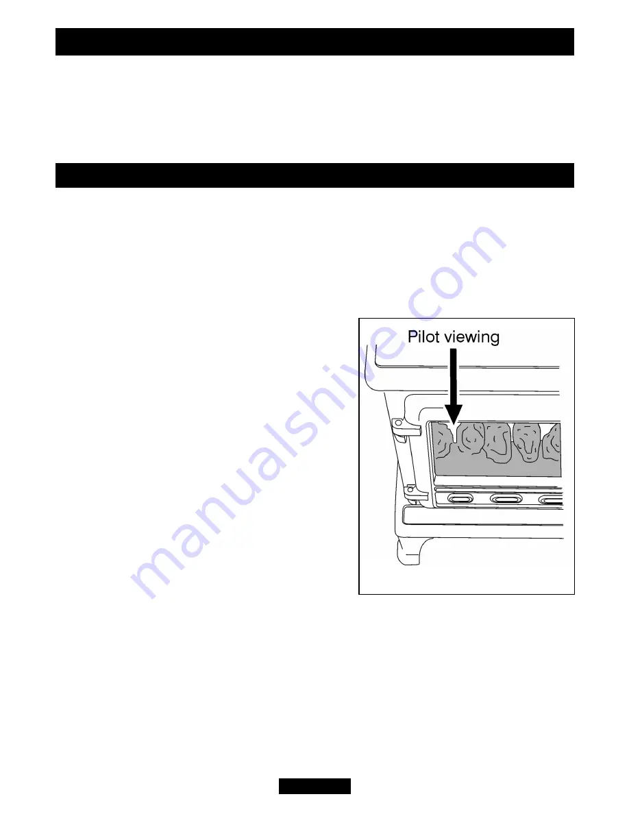
appears at the pilot. The pilot can be seen by
looking through the space in the left hand front of
the fuel effect (See figure 8). There may be a
delay before the pilot lights due to air being
purged from the system. When a flame appears
at the pilot keep the control knob depressed and
hold the pilot ignition position for five seconds.
When the control knob is released the pilot flame
should remain lit.
Operating the burner.
-
When the pilot burner is operating properly, gradually turn the control knob anti-
clockwise to 'HIGH' (Depress the knob slightly to get past the pilot ignition position).
The main burner should now light. Depress the control knob slightly to release from
the 'HIGH' position and turn back (clockwise) to 'LOW'. While turning, the burner
flames should gradually become lower but remain alight. Depress the control knob
slightly to release from the 'LOW' position and turn back (clockwise) to the ‘Pilot
ignition’ position. The main burner should extinguish but the pilot should remain alight.
Page 14
©
GDC Group Ltd. 2014
Figure 8.
INSTALLER GUIDE


