14
3.2.6 HLC LEDs
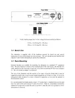
This portion of the front panel is designated to give the
user a visual indication of the HLC results. HLC mode
is described in detail in chapter 4 section 3. The HLC
LEDs are active only when the Hi-Lo comparator mode
(HLC) is activated. The green LED, labeled “GO”, is
on if the measured resistance value is between the
limits
8
set by the user. The yellow LED, labeled
“ExceedLO”, is on if the measured resistance value is less then the lower limit. The red
LED, labeled “ExceedHI”, is on if the measured resistance value is greater then the upper
limit. Only one LED can be on at a time; if more then one LED is on for any length of
time, it is recommended that you contact the Valhalla Scientific Tech Support Team.
3.2.7 Remote LED
The Remote Led indicates the remote/local state of the instrument. If the LED
is on, the instrument is in remote state and can only receive commands
through one of its remote interface ports. If the LED is off, the ohmmeter is in
local state will receive commands only from the front panel keys.
3.2.8 Source and Sense Binding Post
Connections to the 4176 are made via the front
panel source/sense terminals, which consist of
two red and two black standard binding posts
with gold plated brass contact material. The
posts can accept standard banana plugs, wires
up to 12 AWG, or spade lugs. The four
terminals
provide
full
4-Wire
Kelvin
measurement capability. The right posts are the
positive and negative current source terminals
and provide the test current, while the left posts
are the positive and negative voltage sense terminals used to monitor the voltage drop
across the load.
The 4-Wire configuration eliminates errors normally caused by test lead and contact
resistances. In many applications the contact resistance can exceed the value of the load by
several orders of magnitude. The 4176 bypasses this potential error source by providing two
terminals of constant current and an additional two terminals for high impedance voltage
sensing. The result is a fast, accurate resistance measurement of the load, independent of the
8
See chapter 4 section 3.2 for detail on how to set the Hi-Lo limits.


