5
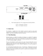
Figure 1 – 4176 Rear Panel
Figure 2 – Line Voltage Switch Position
2.
Verify that the proper fuse for this voltage has been installed as follows:
Fuse
Blo
Slo
Amp
Vac
Fuse
Blo
Slo
Amp
Vac
−
=
−
=
125
.
0
230
250
.
0
115
1.4 Bench Use
The ohmmeter is supplied with all the hardware required for bench use and special
instructions for use in this manner are not necessary. The user should become familiar with
chapters 3 and 4 before attempting to operate the instrument.
1.5 Rack Mounting
Optional brackets are available for mounting the ohmmeter in a standard 19" equipment
rack. The rack mount kit consists of two brackets plus 4 flat head screws. The brackets are
easily installed on the front end of each side rail as show in drawing
№
4176-xxx in chapter
11. The kit is listed in chapter 5 as
Option-R
The size of the ohmmeter and the location of its center of gravity dictate that it must be
supported on both sides along its entire length through the use of trays or slides. If it is to be
transported while mounted in a rack, it should be supported so as to prevent upward or
downward movement.
It is recommended that blank panels at least 1.75 inches high be installed between this and
any other units in the rack to ensure freedom of air flow. Under no circumstances should the
ambient air temperature around the unit exceed 50
°
C while the unit is in operation or 70
°
C
when power is removed.


