Section 4 - Programming
MC122 - MCP-4J Control Unit
32
The Main Menu Buttons
There are 5 Main Menu Buttons. The LED in the upper Left hand side of the Buttons indicates which Main Menu
Button is selected.
Pattern Button - Pressing the Pattern Button allows you to begin to enter gluing patterns for valves 1-4.
Pressure Button - Pressing the Pressure Button allows you to begin to enter the pressure settings.
Setup Button - Pressing the Setup Button allows you to begin to setup the MCP-4J Control Unit.
Diagnostics Button - Pressing the Diagnostics Button allows you to view the MCP-4J Control Unit
diagnostics.
Job Button - Pressing the Job Button allows you to save a job and load a job.
The Valve Buttons
There are 5 Valve Buttons:
Purge Button - Pressing the Purge Button allows you to turn the Manual Purge Mode on and off.
When the Purge Button LED is on, Manual Purge Mode is
on. In this Mode, the Valve Buttons act as “purge buttons.”
When the LED is off, the Valve Buttons turn the valves on
and off.
Valve 1-4 Buttons - Pressing the individual Valve Button(s) allows you to tell the MCP-4J Control Unit
which valves you are going to use for the job you will run. The LED in the upper Left
hand side of the Buttons indicates which valve is selected.
The Navigation Buttons
There are 2 Navigation Buttons: the Right Arrow Button and the Left Arrow Button:
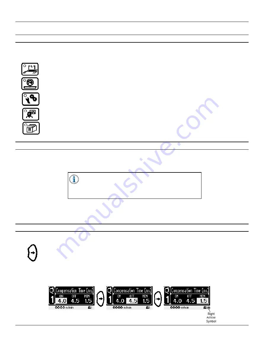
Right Arrow Button - Pressing the Right Arrow Button moves the cursor to the right, highlighting each
editable field (see Figure 4-2A through 4-2C).
When there are no more editable fields on the screen to highlight, a Right Arrow Symbol may appear in
the lower right corner of the screen (see Figure 4-2C). If this Right Arrow Symbol appears, there is an
additional menu screen to the right of the current display. Press the Right Arrow Button to view the menu
screen to the right.
Figure 4-2A
Figure 4-2B
Figure 4-2C
Содержание MCP-4J
Страница 4: ......
Страница 10: ...Table of Contents MC122 MCP 4J Control Unit 6 ...
Страница 12: ...Section 1 Introduction MC122 MCP 4J Control Unit 2 ...
Страница 20: ...Section 2 Safety and Use MC122 MCP 4J Control Unit 10 ...
Страница 38: ...Section 3 Basic features MC122 MCP 4J Control Unit 28 Wiring the Scanner Cable Continued ...
Страница 59: ...MC122 MCP 4J Control Unit Section 4 Programming 49 Protected Level Mode Continued ...
Страница 100: ...Section 6 Maintenance MC122 MCP 4J Control Unit 90 ...
Страница 102: ...Section 7 Specifications MC122 MCP 4J Control Unit 92 ...
Страница 104: ...Section 8 Part Number List MC122 MCP 4J Control Unit 94 MCP 4J Vertical with EPC 074xx084 JWT6119 dwg ...
Страница 107: ...MC122 MCP 4J Control Unit Section 8 Part Number List 97 MCP 4J Vertical w o EPC 074xx085 KMP0153 dwg ...
Страница 110: ...Section 8 Part Number List MC122 MCP 4J Control Unit 100 MCP 4J Vertical 3NC Tipsealer 074xx086 JWT6546 dwg ...
Страница 113: ...MC122 MCP 4J Control Unit Section 8 Part Number List 103 MCP 4J Horizontal with EPC 074xx087 JWT6113 dwg ...
Страница 116: ...Section 8 Part Number List MC122 MCP 4J Control Unit 106 MCP 4J Horizontal w o EPC 074xx088 KMP0154 dwg ...
Страница 122: ...Section 8 Part Number List MC122 MCP 4J Control Unit 112 MCP 4J Horizontal Dual External EPC 074xx090 KMP0159 dwg ...
Страница 130: ...Section 8 Part Number List MC122 MCP 4J Control Unit 120 ...
Страница 132: ...Section 9 Warranty MC122 MCP 4J Control Unit 122 ...
Страница 134: ...Section 10 Service MC122 MCP 4J Control Unit 124 ...
Страница 136: ...Appendix A Job Charts MC122 MCP 4J Control Unit 126 Job Number Job Name Description ...
Страница 146: ...Appendix C Instruction Sheets for the MCP 4J MC122 MCP 4J Control Unit 136 ...
Страница 156: ...MCP 4J Quick Start Guide IS0368 Valco Melton 10 Operator Panel ...


