0020213394_05 Installation and maintenance instructions
23
–
Rated voltage of external brine pressure switch:
230 V 50 Hz
–
Power range for external brine pressure switch (rms):
1 to 5 mA
8.4.6
Connecting a limit thermostat
In some cases where the underfloor heating has a direct
power supply, a limit thermostat (on-site) is essential.
▶
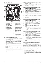
Pull out the S20 plug for the bypass line at terminal X100
on the control PCB.
▶
Connect the limit thermostat at this terminal.
8.4.7
Connecting an external well pump
2
1
Lb La N
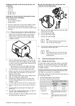
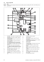
A changeover contact connection X143
(1)
with the assign-
ment Lb, La, N, PE is provided for connecting a cut-off relay
for the external well pump.
Lb is the opening contact. If the cut-off relay contact to the
well pump is closed, there is no voltage at Lb.
La is the closing contact. If the cut-off relay contact to the
well pump is closed, there is no voltage at La.
The X200
(2)
connection for the optional VR 11 temperature
sensors, which are available as accessories, is labelled RR
for return connections and VV for flow connections.
▶
Connect a cut-off relay for the external well pump to the
X143 connection.
–
Max. switching capacity at plug output: 1 A
▶
Connect the temperature sensors to the VV (suction well)
and RR (injection well) terminals.
–
Terminal assignment for terminal X200 on the power
supply PCB
–
Terminal 1 + 2: Well inlet temperature
–
Terminal 3 + 4: Well outlet temperature
Note
No functions are coupled to these temperature
sensors for monitoring the heat source. They
are simply shown on the display.
8.4.8
Connecting the temperature sensor for
an external domestic hot water cylinder
(optional)
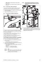
1
2
X2
2
▶
Connect the cable for the cylinder temperature sensor,
which is available as an accessory, to the bush
(1)
on the
plug
(2)
. Use a strain relief which does not have a power
supply cable running through it.


