


Appendix
0020213394_01 flexoTHERM exclusive Installation and maintenance instructions
67
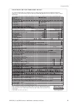
VWF 57/4
VWF 87/4
VWF 117/4
VWF 157/4
VWF 197/4
Max. heating mode target flow temperat-
ure with external auxiliary heater
75
℃
75
℃
75
℃
75
℃
75
℃
Max. heating mode target flow temperat-
ure without auxiliary heater
65
℃
65
℃
65
℃
65
℃
65
℃
Min. cooling mode flow temperature
5
℃
5
℃
5
℃
5
℃
5
℃
Max. electrical power consumption, heat-
ing pump
63 W
63 W
63 W
140 W
140 W
Heating pump type
High-efficiency
pump
High-efficiency
pump
High-efficiency
pump
High-efficiency
pump
High-efficiency
pump
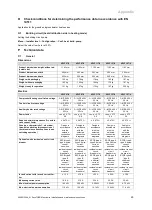
Refrigeration circuit
VWF 57/4
VWF 87/4
VWF 117/4
VWF 157/4
VWF 197/4
Coolant type
R410A
R410A
R410A
R410A
R410A
Coolant content of the coolant circuit in
the heat pump
1.50 kg
2.40 kg
2.50 kg
3.05 kg
3.95 kg
Global warming potential (GWP) in
accordance with regulation (EU) no.
517/2014
2088
2088
2088
2088
2088
CO
₂
equivalent
3132
5011
5220
6368
8248
Global warming potential 100 (GWP
100
)
in accordance with regulation (EC) no.
842/2006
1975
1975
1975
1975
1975
Expansion valve design
Electronic
Electronic
Electronic
Electronic
Electronic
Permissible operating pressure (relative)
≤
4.6 MPa
(
≤
46.0 bar)
≤
4.6 MPa
(
≤
46.0 bar)
≤
4.6 MPa
(
≤
46.0 bar)
≤
4.6 MPa
(
≤
46.0 bar)
≤
4.6 MPa
(
≤
46.0 bar)
Compressor type
Scroll
Scroll
Scroll
Scroll
Scroll
Oil type
Ester
(EMKARATE
RL32-3MAF)
Ester
(EMKARATE
RL32-3MAF)
Ester
(EMKARATE
RL32-3MAF)
Ester
(EMKARATE
RL32-3MAF)
Ester
(EMKARATE
RL32-3MAF)
Oil filling quantity
0.75 l
1.25 l
1.25 l
1.24 l
1.89 l
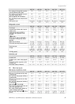
Installation site
VWF 57/4
VWF 87/4
VWF 117/4
VWF 157/4
VWF 197/4
Installation site
Interior/dry
Interior/dry
Interior/dry
Interior/dry
Interior/dry
Installation room volume complying with
EN 378
3.41 m
³
5.45 m
³
5.68 m
³
6.93 m
³
8.98 m
³
Permissible ambient temperature at the
installation site
7 … 25
℃
7 … 25
℃
7 … 25
℃
7 … 25
℃
7 … 25
℃
Permissible relative air humidity
40 … 75 %
40 … 75 %
40 … 75 %
40 … 75 %
40 … 75 %
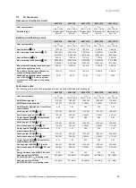
P.2
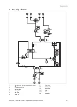
Brine heat source
Heat source circuit/brine circuit
VWF 57/4
VWF 87/4
VWF 117/4
VWF 157/4
VWF 197/4
Min. source inlet temperature (hot brine)
in heating mode
−
10
℃
−
10
℃
−
10
℃
−
10
℃
−
10
℃
Max. source inlet temperature (hot brine)
in heating mode
25
℃
25
℃
25
℃
25
℃
25
℃
Min. source inlet temperature (hot brine)
in cooling mode
0
℃
0
℃
0
℃
0
℃
0
℃
Max. source inlet temperature (hot brine)
in cooling mode
30
℃
30
℃
30
℃
30
℃
30
℃
Nominal flow
Δ
T 3 K for B0/W35
1,290 l/h
2,320 l/h
3,000 l/h
3,590 l/h
4,780 l/h
Min. volume flow during continuous oper-
ation at the application limits
1,110 l/h
2,140 l/h
2,460 l/h
3,380 l/h
3,840 l/h
Max. volume flow during continuous op-
eration at the application limits
1,290 l/h
2,320 l/h
3,000 l/h
3,590 l/h
4,780 l/h
Max. remaining feed head with
Δ
T 3 K for
B0/W35
0.062 MPa
(0.620 bar)
0.039 MPa
(0.390 bar)
0.051 MPa
(0.510 bar)
0.098 MPa
(0.980 bar)
0.082 MPa
(0.820 bar)