background image

For the competent person

Installation and maintenance instructions

flexoTHERM exclusive

VWF 57/4

VWF 87/4

VWF 117/4

VWF 157/4

VWF 197/4

GB, IE

Installation and maintenance instructions

Publisher/manufacturer
Vaillant GmbH

Berghauser Str. 40

D-42859 Remscheid

Tel. +49

21

91

18

0

Fax +49

21

91

18

2810

[email protected]

www.vaillant.de

Содержание flexoTHERM exclusive VWF 117/4

Страница 1: ...ons flexoTHERM exclusive VWF 57 4 VWF 87 4 VWF 117 4 VWF 157 4 VWF 197 4 GB IE Installation and maintenance instructions Publisher manufacturer Vaillant GmbH Berghauser Str 40 D 42859 Remscheid Tel 49 21 91 18 0 Fax 49 21 91 18 2810 info vaillant de www vaillant de ...

Страница 2: ... 10 Installing optional accessories 28 8 11 Checking the electrical installation 28 8 12 Completing installation 28 9 Start up 29 9 1 Operating concept 29 9 2 Starting up the heat pump system 29 9 3 Running the installation assistants 29 9 4 Calling up the installer level 30 9 5 Heating mode flow temperature regulation 30 9 6 Calling up statistics 30 9 7 Checking that the product works correctly 3...

Страница 3: ...erature sensor 54 J Characteristic values for internal temperature sensors 55 K Characteristic values for the VRC DCF outdoor temperature sensor 56 L Heat pump schematic 57 M Commissioning Checklist 59 N Commissioning Checklist 62 O Check conditions for determining the performance data in accordance with EN 14511 65 O 1 Building circuit heat distribution side in heating mode 65 P Technical data 65...

Страница 4: ...r system compon ents installing and fitting the product in accord ance with the product and system approval compliance with all inspection and main tenance conditions listed in the instruc tions Intended use also covers installation in ac cordance with the IP class Any other use that is not specified in these instructions or use beyond that specified in this document shall be considered improper u...

Страница 5: ...ufficient load bearing capacity to bear the operating weight of the product 1 3 8 Danger due to malfunctions Ensure that the heating installation is in a technically perfect condition Ensure that no safety or monitoring devices have been removed bridged or disabled Immediately rectify any faults and damage that may affect safety Install the controller in a location where it is not covered by furni...

Страница 6: ... tocol with a GWP of 2088 GWP global warming potential If this gas escapes into the atmosphere its impact is 2088 times greater than the natural greenhouse gas CO2 Before the product is disposed of the coolant that is contained in it must be completely drained into a suitable vessel so that it can then be recycled or disposed of in accord ance with regulations Ensure that only officially certified...

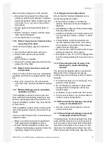
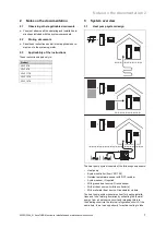
Страница 7: ...4 VWF 117 4 VWF 157 4 VWF 197 4 3 System overview 3 1 Heat pump system design A B A B The heat pump system consists of the following components Heat pump System controller from VRC 700 Outside temperature sensor with DCF receiver System sensor if required With ground heat source Ground sensor With air heat source Air brine collector s With well water heat source Groundwater module The heat pump sy...

Страница 8: ...ump 2 3 1 4 5 6 7 8 9 10 11 12 13 1 Heating installation 2 Domestic hot water cylinder optional 3 Heating circuit 4 Compressor 5 Refrigeration circuit 6 Brine circuit 7 Heat source 8 Brine pump 9 Evaporator 10 Electronic expansion valve 11 Condenser 12 Heating cylinder char ging diverter valve 13 Auxiliary electric heating The heat pump system uses geothermal energy outdoor air or groundwater as t...

Страница 9: ... it may be useful to exclude some rooms e g the bathroom from the cooling function and to actuate stop valves especially for this The heat pump elec tronics system emits a signal that can be used for actuating these A passive cooling module is also available as an alternative whereby thermal energy is transported via underfloor heat ing for example from the rooms to the ground without the compress...

Страница 10: ...t exceeds the maximum temperature the hot gas thermostat temporar ily shuts down the heat pump Following a waiting period another attempt is made to start the heat pump After three failed start attempts in succession a fault message is dis played Max refrigeration circuit temperature 135 Waiting period 5 minutes after the first occurrence Waiting period 30 minutes after the second and every furthe...

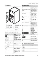
Страница 11: ...g B0 W35 W45 W55 Heating output at a brine temperature of X C and a heating flow temperature of XX C COP A2 W35 A7 W35 A7 W45 A7 W55 Output figure Coefficient of Performance at an air temperature of X C and a heating flow temperature of XX C EER A35 W1835 Output figure Energy Effi ciency Ratio at an air tem perature of XX C and a heating flow temperature of XX C A2 W35 A7 W35 A7 W45 A7 W55 Heating...

Страница 12: ...he Benchmark Code of Practice which is available from the Heating and Hotwater Industry Council who manage and promote the Scheme Benchmark is managed and promoted by the Heating and Hotwater Industry Council For more information visit www centralheating co uk 5 Installation 5 1 Checking the scope of delivery 1 Carefully remove the packaging and padding without damaging the parts of the product 2 ...

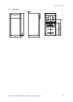
Страница 13: ...Installation 5 0020213394_01 flexoTHERM exclusive Installation and maintenance instructions 13 5 3 Dimensions 671 651 595 600 20 833 1183 18 2 91 100 100 91 25 50 90 115 115 90 ...

Страница 14: ...uck at the rear so that the weight dis tribution is as even as possible Secure the product using a retaining strap Use a ramp to move the product from the pallet using the sack truck e g a piece of square timber and a sturdy board 5 5 1 Using the carrying straps 1 Remove the front casing Page 15 Danger Risk of injury due to repeated use of the carrying straps Due to material ageing the carrying st...

Страница 15: ...the front casing 1 1 Remove the front flap on the operator control panel by taking hold of the recessed handles with both hands and lifting off the front flap towards you 4x 2 Turn the four screws by a quarter turn and lift off the cover on the operator control panel towards you A B 3 Pull each part of the front casing forwards slightly and remove it by lifting it upwards 5 9 Removing the casing t...

Страница 16: ...ccordance with the dimension and connec tion drawings Position the pipe brackets for securing the heating circuit and brine circuit piping so that they are not too close to the heat pump in order to prevent noise transmission If required instead of pipe brackets use cold insu lation clamps with additional rubber insulation and in some cases reinforced hoses armoured rubber hoses To prevent excessi...

Страница 17: ...ulate all of the brine lines and the connections of the heat pump so that they are vapour diffusion tight Note Vaillant recommends that you install the Vaillant heat pump brine filling unit not required when installing the groundwater module By doing this it is then possible to carry out a preparatory partial bleed of the brine circuit e g the flow and return lines of the brine circuit to the prod...

Страница 18: ... any unsuitable frost and cor rosion protection agents biocides or seal ants No incompatibility with our products has been detected to date with proper use of the following additives When using additives follow the manufacturer s instruc tions without exception We accept no liability for the compatibility of any additive or its effectiveness in the rest of the heating system Additives for cleaning...

Страница 19: ...rom Vaillant Use a sufficiently large mixing container Carefully mix ethylene glycol with water Approved environment source Ground groundwater module Air brine collector Brine content 30 vol 44 vol Water content 70 vol 56 vol Cloud point of the aqueous ethylene glycol mixture 16 C 30 C Cold protection of the aqueous ethyl ene glycol mixture 18 C 33 5 C Cloud point Cold protection Above this temper...

Страница 20: ...rine fluid 8 Electrical installation Danger Risk of death from electric shock caused by a residual current circuit breaker not working In certain cases residual current circuit breakers may not work If residual current circuit breakers are re quired to ensure that people are protec ted and fire is prevented in line with the applicable standards use type A pulse current sensitive residual current c...

Страница 21: ...y it can be connected here 2 Controller PCB 3 VR 40 multi functional module 2 in 7 op tional Relay 1 is used as a fault contact connec tion alarm output for the heat pump The func tion of relay 2 can be set on the system con troller 4 In rush current limiter PCB 5 Line protection switch 6 Mains connection PCB 7 Mains connection ter minal for the auxiliary electric heater 8 4 Establishing the power...

Страница 22: ...ure switch In some cases for example in drinking water protection areas local authorities require the installation of an external brine pressure switch that switches off the refrigerant circuit if the pressure in the brine circuit falls below a certain level If the circuit is switched off by the brine pressure switch a fault message is shown on the display Pull out the X131 plug for the bypass lin...

Страница 23: ...instructions 23 8 4 8 Connecting the temperature sensor for an external domestic hot water cylinder optional 1 2 X22 Connect the cable on the VR 10 temperature sensor supplied as an accessory to bush 1 on plug 2 Use a strain relief which does not have a mains voltage line running through it ...

Страница 24: ...ternal auxiliary electric heating 2 X110B Optional bridge to X110 230 V supply for electronics system 3 X120 Optional 230 V supply for protection anode active tank anode 4 F1 F1 T 4A 250 V fuse protects 230 V loads on mains connection PCB 5 X110 Mains connection for 230 V electronics sys tem mains connection PCB TB and controller PCB HMU 6 X110A Bridge to X110 230 V supply for electron ics system ...

Страница 25: ...Optional temperature sensors for groundwa ter module 17 X203 Optional flow temperature sensor for heating circuit with passive cooling module 18 X202 not used 19 X90 not used 20 X140 Connection for 3 way diverter valve for pass ive cooling module 21 X142 3 way mixer valve for passive cooling module 22 X104 Internal auxiliary electric heating connection 23 X131 Optional external brine pressure swit...

Страница 26: ...R40 edge connector electrical lines 3 X51 Edge connector for display connection 4 X30 eBUS connection diagnostics interface 5 X25 Modbus plug for controlling the in rush current limiter 6 X31 not used 7 X24 not used 8 X41 Edge connector for external sensors outside temperature sensor DCF system sensor multi function input can be adjusted in the system con troller 9 X26 Sensor cable harness 10 X100...

Страница 27: ...onnection for internal 3 way valve for hot water DHW 16 X13 Internal brine pump connection 17 X16 Internal heating pump connection 18 X11 Connection for internal 4 way valve 19 X1 230 V supply for controller PCB 20 F1 F1 T 4A 250 V fuse 21 X12 Edge connector for 230 V supply for optional VR 40 22 X22 Connection for sensor cable harness includ ing connection for internal VR 10 cylinder temperat ure...

Страница 28: ...l conductors are sitting mechanically securely in the terminals of the plug Remedy this if necessary 11 Plug the plug into the associated PCB slot 8 9 Installing the VRC DCF Install the VRC DCF receiver in accordance with the in stallation instructions for the system controller 8 10 Installing optional accessories 1 Route the lines through the ducts in the back wall of the product 2 Open the elect...

Страница 29: ...g ground brine as the heat source active cooling is limited to a brine output temperature of 40 C in order to protect the source probe borehole If this temperature is ex ceeded 40 C active cooling mode is switched off This limit can only be changed by Vaillant Customer service 9 3 4 Enabling auxiliary electric heating On the system controller you can select whether the auxili ary electric heating ...

Страница 30: ...ating demand only just arises from the controller e g due to a time period or switching the gas fired boiler operation to heat pump mode Time conditions for compressor operation The following shall always apply for operation Minimum running time 3 minutes Minimum rest period 7 minutes Minimum time from start to start 20 minutes 9 6 Calling up statistics Menu Installer level Test menu Statistics Yo...

Страница 31: ...l flow 0 100 200 300 400 500 600 700 800 40 50 60 70 80 90 100 B A 1 2 3 1 Air heat source 2 Ground heat source 3 Groundwater heat source A Remaining feed head in hPa mbar B Pump output in 10 2 2 3 Remaining feed head for VWF 11x 4 building circuit pump at nominal flow 0 100 200 300 400 500 600 700 800 40 50 60 70 80 90 100 B A 1 2 3 1 Air heat source 2 Ground heat source 3 Groundwater heat source...

Страница 32: ...ment circuit pump depends on the environment circuit type set and the output range Navigate to the Menu Installer level Configuration Env pump target val menu point If necessary change the factory setting and confirm by pressing 10 2 4 Remaining feed head of environment circuit pump 10 2 4 1 Remaining feed head for VWF 5x 4 environment circuit pump at nominal flow 0 100 200 300 400 500 600 700 800...

Страница 33: ... mode 2 Press twice The display shows the value of the flow temperature in cooling mode 3 Change the flow temperature in cooling mode by press ing or 4 Confirm this change by pressing OK Note At the factory the target flow temperature can be set to between 20 C and 16 C in passive cooling mode 10 5 Handing the product over to the operator Explain to the operator how the safety devices work and whe...

Страница 34: ...A circuit breaker is used to secure the internal auxiliary elec tric heater against short circuits If the circuit breaker has been triggered the auxiliary electric heater remains switched off until the short circuit has been rectified and the circuit breaker in the electronics box has been manually reset 11 8 1 Resetting the circuit breaker in the auxiliary electric heater 1 Check the supply line ...

Страница 35: ...the brine fluid and the pressure in the brine circuit Top up with brine fluid if required x x 5 Check that the expansion vessel and the expansion relief valve in the brine circuit are working correctly x x 6 Check that the expansion vessel and the expansion relief valve in the heating circuit are working correctly x x No Work Inspection every year within 24 months at the latest Main tenance every ...

Страница 36: ...t or the accessories with household waste Dispose of the product and all accessories correctly Observe all relevant regulations 14 1 Disposing of the brine fluid Danger Risk of injury due to chemical burns The brine fluid ethylene glycol is harmful to health Avoid contact with the skin and eyes Do not inhale or swallow Always wear gloves and protective goggles Observe the safety data sheet that ac...

Страница 37: ...troller PCB X110 X101 Mains connection for compressor X103 Optional power output for internal auxiliary electric heating X102 X102 Mains connection for internal auxiliary electric heat ing X110 Mains connection for heat pump controller PCB This is how it is wired when supplied The product is connected to the supply network using a single electricity tariff a con sumption meter The internal auxilia...

Страница 38: ...er output for internal auxiliary electric heating X102 X102 Mains connection for internal auxiliary electric heat ing X110 Mains connection for heat pump controller PCB In this case the heat pump is operated using two electricity tariffs two consumption meters A continuous power supply ensures the operation of the internal auxiliary electric heating and the controller PCB of the heat pump via its ...

Страница 39: ...utput for internal auxiliary electric heating X102 X102 Mains connection for internal auxiliary electric heat ing X110 Mains connection for heat pump controller PCB In this case the heat pump is operated using two electricity tariffs two consumption meters A continuous power supply ensures the operation of the auxiliary consumers circulation pumps controllers etc via a sep arate electricity meter ...

Страница 40: ... case the heat pump is operated using two electricity tariffs two consumption meters A continuous power supply ensures the operation of the compressor and the controller PCB of the heat pump via its own electricity meter The power from the additional blockable power supply for the internal auxiliary electric heating is supplied via a second elec tricity meter and can be suspended by the power supp...

Страница 41: ...nsion valve injection steps Current value VUV DHW switchings Current value Well pump hours Current value h Well pump starts Current value Heat rod power cons Current value kWh Heat rod switchings Current value Heat rod op hours Current value h Installer level Test menu Check programmes P 01 Heating mode Select P 02 Cooling mode Select P 03 Hot water handling Select P 04 Heating rod Select P 05 Pur...

Страница 42: ...48 Circulation pump Off On Off On Off T 49 Relay Cooling active only for passive or active cooling Off On Off On Off Sensors Building circuit sensors T 79 Flow temperature 40 90 0 1 T 80 Cooling flow temperature only for passive cooling 40 90 0 1 T 81 Return temperature 40 90 0 1 T 82 Building circuit Pressure 0 4 5 bar 0 1 T 83 Building circuit Flow rate 0 4000 l h 1 T 84 Lockout contact S20 Open...

Страница 43: ...0 1 T 123 EEV VI inlet temperature 40 90 0 1 T 124 EEV VI outlet temperature 40 90 0 1 T 127 High pressure 0 47 bar abs 0 1 T 128 Condensation temperature 40 70 0 1 T 129 Low pressure 0 47 bar abs 0 1 T 130 Evaporation temperature 40 90 0 1 T 131 Superheating target value 40 90 K 0 1 T 132 Superheating actual value 40 90 K 0 1 to 20 K are normal op erating parameters T 134 High pressure switch Clo...

Страница 44: ...es External 2 kW 3 5 kW 5 5 kW 7 kW 9 kW 9 Enviro pump set p 1 100 1 Air brine VWF 57 4 55 VWF 87 4 78 VWF 117 4 86 VWF 157 4 47 VWF 197 4 68 Ground brine VWF 57 4 100 VWF 87 4 100 VWF 117 4 100 VWF 157 4 100 VWF 197 4 100 Well VWF 57 4 47 VWF 87 4 100 VWF 117 4 100 VWF 157 4 47 VWF 197 4 74 Conf fan Auto 1 100 1 Auto Noise reduction fan 0 40 1 20 Freeze protection Ground brine 14 Air brine 28 Wel...

Страница 45: ...cond fan unit OMU2 xxxx xx xx Installer level Resets Blocking times reset Yes No No Statistics reset Yes No No Factory settings Yes No No Installer level Start inst assistant Language Languages available for selection 02 English Enviro circuit type Select Air brine Ground brine Well Freeze protection Ground brine 14 Air brine 28 Well 2 5 1 Ground brine 7 Air brine 28 Well 2 Heat rod outp range Ext...

Страница 46: ... Compressor shutdown S 112 Cooling Compressor blocked S 113 Cooling Compressor mode flow S 114 Cooling Compressor active S 117 Cooling Compressor mode overrun S 118 Cooling Flow S 119 Cooling Mixer active S 125 Heating Heating rod active S 131 Hot water Compressor shutdown S 132 Hot water Compressor blocked S 133 Hot water Flow S 134 Hot water Compressor active S 135 Hot water Heating rod active S...

Страница 47: ...mp too high S 264 Fan unit 2 Air inlet temp too low S 265 Environment circuit Pressure mon open S 266 Environment cir inlet temperature too high Displays relating to the building circuit S 272 Building circuit Remaining feed heads limit active S 273 Building circuit Flow temperature too low S 274 Building circuit Pressure too low S 275 Building circuit Flow rate too low S 276 Building cir Lockout ...

Страница 48: ...rrectly and if required replace the pressure sensor M 49 Only with the heat source Air Environment circuit Brine lines inverted Check that the connections are correctly assigned to the brine lines H Fault codes Note In the event of rare faults which are caused by components in the refrigeration circuit inform Customer Service Code Meaning Cause Remedy F 070 Invalid Device Specific Number Replacing...

Страница 49: ... cir pres sure Sensor not connected or sensor input has short circuited Check the sensor and replace if necessary Replace the cable harness F 705 Sensor fault Enviro cir pressure Sensor not connected or sensor input has short circuited Check the sensor and replace if necessary Replace the cable harness F 708 Connection error Fan unit 1 No electrical connection No eBUS connection Check the electric...

Страница 50: ... 723 Building circuit Pressure too low Pressure loss in the building circuit due to leaks or air pockets Building circuit pressure sensor defective Check the building circuit for leaks Top up with water purge Check the quality of the plug contact on the PCB and on the cable har ness Check that the pressure sensor is working correctly Replace the pressure sensor F 724 Sensor fault Fan unit 1 fan in...

Страница 51: ...t Check the compressor inlet sensor and low pressure sensor F 740 Environment cir inlet temperature too low Inlet temperature in the environment circuit too low for the compressor to start for heating Air brine Environment circuit inlet temperature 28 C Ground brine Environment circuit inlet temperature 7 C Groundwater brine Groundwater inlet temperature 2 C Check the dimensioning of the envir onm...

Страница 52: ...as soon as the temperature at the fuse falls below 30 C again If the safety cut out is still open at a de icer temperature below 65 C or 30 C temperatures above 115 C were reached and the fuse tripped Check and if required replace the F1 fuse of the air brine collector Replace the safety cut out F 787 Environment circuit Pressure mon open Pressure loss in the environment circuit due to leaks or ai...

Страница 53: ... above 110 C were reached and the fuse tripped Replace the safety cut out Reduce or stop the external heat that is entering F 1117 Compressor Phase failure In rush current limiter defective or incorrectly connected Defective fuse Poorly tightened electrical connec tions Mains voltage too low Compressor low tariff power supply not connected Blocked by energy supply company for over three hours Chec...

Страница 54: ...re sensor Temperature C Resistance ohms 40 87879 35 63774 30 46747 25 34599 20 25848 15 19484 10 14814 5 11358 0 8778 5 6836 10 5363 15 4238 20 3372 25 2700 30 2176 35 1764 40 1439 45 1180 50 973 55 807 60 672 65 562 70 473 75 400 80 339 85 289 90 247 95 212 100 183 105 158 110 137 115 120 120 104 125 92 130 81 135 71 140 63 145 56 150 50 155 44 ...

Страница 55: ...perature C Resistance ohms 40 327344 35 237193 30 173657 25 128410 20 95862 15 72222 10 54892 5 42073 0 32510 5 25316 10 19862 15 15694 20 12486 25 10000 30 8060 35 6535 40 5330 45 4372 50 3605 55 2989 60 2490 65 2084 70 1753 75 1481 80 1256 85 1070 90 916 95 786 100 678 105 586 110 509 115 443 120 387 125 339 130 298 135 263 140 232 145 206 150 183 ...

Страница 56: ...ructions flexoTHERM exclusive 0020213394_01 K Characteristic values for the VRC DCF outdoor temperature sensor Temperature C Resistance ohms 25 2167 20 2067 15 1976 10 1862 5 1745 0 1619 5 1494 10 1387 15 1246 20 1128 25 1020 30 920 35 831 40 740 ...

Страница 57: ...TT 11 TZ 11 PZ 11 PT 11 TT 14 TT 10 PT 10 TT 17 TT 30 PT 30 TT 31 TT 20 PT 20 TT 21 TZ 21 M C S E D V7 TCE CP2 1 3 2 4 5 6 FLT1 FLT2 1 Heating circuit diaphragm expansion tank connec tion 2 Circulation connection 3 Heating return 4 Heating flow 5 Hot brine 6 Cold brine C1 Compressor CP1 Heating pump CP2 Brine pump FLT1 Filter FLT2 Filter HE1 Condenser ...

Страница 58: ...perature sensor TT11 Compressor outlet temperature sensor TT14 Intermediate injection compressor inlet temperature sensor TT17 Electronic expansion valve outlet temperature sensor TT20 Heating return temperature sensor TT21 Heating flow temperature sensor TT30 Source inlet temperature sensor TT31 Source outlet temperature sensor TZ11 Compressor outlet temperature switch TZ21 Safety cut out tempera...

Страница 59: ...d maintenance instructions 59 M Commissioning Checklist Heating and Hotwater Industry Council HHIC www centralheating co uk Benchmark Commissioning and Servicing Section It is a requirement that the boiler is installed and commissioned to the completed in full ...

Страница 60: ... ZHLJKW Yes 7KH V VWHP KDV EHHQ ÀXVKHG DQG FOHDQHG LQ DFFRUGDQFH ZLWK 6 DQG KHDW SXPS PDQXIDFWXUHU V LQVWUXFWLRQV Yes What system cleaner was used What inhibitor was used Quantity litres Is the system adequately frost protected Yes OUTDOOR UNIT Are all external pipeworks insulated Yes Is the fan free from obstacles and operational Yes Has suitable consideration been made for waste water discharge ...

Страница 61: ... Engineer name Company name Telephone No 2SHUDWLYH 1R Comments Signature SERVICE 05 Date Engineer name Company name Telephone No 2SHUDWLYH 1R Comments Signature SERVICE 07 Date Engineer name Company name Telephone No 2SHUDWLYH 1R Comments Signature SERVICE 09 Date Engineer name Company name Telephone No 2SHUDWLYH 1R Comments Signature SERVICE 02 Date Engineer name Company name Telephone No 2SHUDWL...

Страница 62: ...THERM exclusive 0020213394_01 N Commissioning Checklist Heating and Hotwater Industry Council HHIC www centralheating co uk Benchmark Commissioning and Servicing Section It is a requirement that the boiler is installed and commissioned to the completed in full ...

Страница 63: ...V KDYH EHHQ OOHG DQG SUHVVXUH WHVWHG LQ DFFRUGDQFH ZLWK UHOHYDQW ULWLVK 6WDQGDUGV Yes I PRUH WKDQ RQH FROOHFWRU KDV EHHQ XVHG KDV WKH V VWHP EHHQ K GUDXOLFDOO EDODQFHG ORZ EDODQFLQJ UHJXODWLQJ YDOYHV WWHG DGMXVWHG Yes Has the system been vented de aired Yes UH V VWHP OWHUV WWHG FOHDQ Yes Is the system topped up to the correct level Yes DV WKH V VWHP FOHDQHG ÀXVKHG SULRU WR XVH Yes Are isolating va...

Страница 64: ...Date Engineer name Company name Telephone No 2SHUDWLYH 1R Comments Signature SERVICE 05 Date Engineer name Company name Telephone No 2SHUDWLYH 1R Comments Signature SERVICE 07 Date Engineer name Company name Telephone No 2SHUDWLYH 1R Comments Signature SERVICE 09 Date Engineer name Company name Telephone No 2SHUDWLYH 1R Comments Signature SERVICE 02 Date Engineer name Company name Telephone No 2SH...

Страница 65: ...rk impedance Zmax with in rush current limiter 0 472 Ω 0 472 Ω 0 472 Ω 0 472 Ω 0 472 Ω Fuse type characteristic C slow blow three pole switching disconnection of the three mains connection lines in one switching operation Design in accordance with the selected connection diagrams Design in accordance with the selected connection diagrams Design in accordance with the selected connection diagrams D...

Страница 66: ...lding circuit heating circuit VWF 57 4 VWF 87 4 VWF 117 4 VWF 157 4 VWF 197 4 Heating circuit water contents in the heat pump 3 2 l 3 9 l 4 4 l 5 8 l 6 5 l Heating circuit materials Cu CuZn Alloy Stainless Steel EPDM Brass Fe Cu CuZn Alloy Stainless Steel EPDM Brass Fe Cu CuZn Alloy Stainless Steel EPDM Brass Fe Cu CuZn Alloy Stainless Steel EPDM Brass Fe Cu CuZn Alloy Stainless Steel EPDM Brass F...

Страница 67: ...Scroll Scroll Scroll Oil type Ester EMKARATE RL32 3MAF Ester EMKARATE RL32 3MAF Ester EMKARATE RL32 3MAF Ester EMKARATE RL32 3MAF Ester EMKARATE RL32 3MAF Oil filling quantity 0 75 l 1 25 l 1 25 l 1 24 l 1 89 l Installation site VWF 57 4 VWF 87 4 VWF 117 4 VWF 157 4 VWF 197 4 Installation site Interior dry Interior dry Interior dry Interior dry Interior dry Installation room volume complying with ...

Страница 68: ... clean heat exchangers VWF 57 4 VWF 87 4 VWF 117 4 VWF 157 4 VWF 197 4 Heating output B0 W35 ΔT 5 K 5 30 kW 8 90 kW 11 20 kW 14 50 kW 19 70 kW Power consumption B0 W35 ΔT 5 K 1 30 kW 2 00 kW 2 50 kW 3 40 kW 4 70 kW Output figure B0 W35 ΔT 5 K coefficient of performance EN 14511 4 70 5 10 5 00 4 90 4 70 Heating output B0 W45 ΔT 5 K 5 30 kW 8 80 kW 11 20 kW 14 10 kW 19 60 kW Power consumption B0 W45...

Страница 69: ...erformance data The following performance data is applicable to new products with clean heat exchangers VWF 57 4 VWF 87 4 VWF 117 4 VWF 157 4 VWF 197 4 Heat source module 1 x VWL 11 4 SA 1 x VWL 11 4 SA 1 x VWL 11 4 SA 2 x VWL 11 4 SA 2 x VWL 11 4 SA A2 W35 heating output 5 70 kW 7 80 kW 10 30 kW 13 90 kW 17 40 kW A2 W35 power consumption 1 40 kW 2 10 kW 2 70 kW 3 50 kW 4 80 kW A2 W35 output figur...

Страница 70: ... 4 SI VWW 11 4 SI VWW 19 4 SI VWW 19 4 SI Nominal flow of groundwater at ΔT 3 K with W10W35 1 450 l h 2 240 l h 3 520 l h 4 540 l h 5 480 l h Brine fluid type Ethylene glycol 30 vol Ethylene glycol 30 vol Ethylene glycol 30 vol Ethylene glycol 30 vol Ethylene glycol 30 vol Building circuit heating circuit VWF 57 4 VWF 87 4 VWF 117 4 VWF 157 4 VWF 197 4 Heat source module VWW 11 4 SI VWW 11 4 SI VW...

Страница 71: ...n W10 W55 ΔT 8 K 2 10 kW 3 00 kW 3 90 kW 4 80 kW 6 80 kW Output figure W10 W55 ΔT 8 K coefficient of performance EN 14511 3 00 3 50 3 30 3 60 3 50 Sound power level W10 W35 EN 12102 EN 14511 LWI in heating mode 41 2 dB A 47 9 dB A 45 0 dB A 49 9 dB A 50 6 dB A Sound power level W10 W45 EN 12102 EN 14511 LWI in heating mode 40 9 dB A 50 3 dB A 47 8 dB A 48 0 dB A 47 8 dB A Sound power level W10 W55...

Страница 72: ...6 0 21 2 0 6 0 0 15 2 6 0 6 0 6 0 5 5 kW 15 3 6 0 21 2 9 3 0 0 15 2 6 0 6 0 6 0 7 0 kW 6 6 21 2 21 2 0 6 15 2 15 2 6 0 6 0 6 0 9 0 kW 15 3 21 2 21 2 9 3 15 2 15 2 6 0 6 0 6 0 X12 max 1 3 A X14 max 0 9 A X141 X143 X144 X145 max 2 5 A 0 0 kW 11 3 6 0 6 0 5 3 0 0 0 0 6 0 6 0 6 0 2 0 kW 20 0 6 0 6 0 14 0 0 0 0 0 6 0 6 0 6 0 3 5 kW 11 3 6 0 21 2 5 3 0 0 15 2 6 0 6 0 6 0 5 5 kW 20 0 6 0 21 2 14 0 0 0 15...

Страница 73: ...0 25 2 5 6 0 0 15 2 10 0 10 0 10 0 5 5 kW 24 3 10 0 25 2 14 3 0 0 15 2 10 0 10 0 10 0 7 0 kW 15 6 25 2 25 2 5 6 15 2 15 2 10 0 10 0 10 0 9 0 kW 24 3 25 2 25 2 14 3 15 2 15 2 10 0 10 0 10 0 VWF 197 4 400 V 0 0 kW 16 1 15 2 15 2 0 9 0 0 0 0 15 2 15 2 15 2 2 0 kW 24 8 15 2 15 2 9 6 0 0 0 0 15 2 15 2 15 2 3 5 kW 16 1 15 2 30 4 0 9 0 0 15 2 15 2 15 2 15 2 5 5 kW 24 8 15 2 30 4 9 6 0 0 15 2 15 2 15 2 15...

Страница 74: ...0 15 2 6 6 6 0 6 0 5 5 kW 0 6 14 7 6 0 21 2 8 7 0 0 15 2 6 6 6 0 6 0 7 0 kW 0 6 6 0 21 2 21 2 0 0 15 2 15 2 6 6 6 0 6 0 9 0 kW 0 6 14 7 21 2 21 2 8 7 15 2 15 2 6 6 6 0 6 0 X12 max 1 3 A X14 max 0 9 A X141 X143 X144 X145 max 2 5 A 0 0 kW 5 3 6 0 6 0 6 0 0 0 0 0 0 0 11 3 6 0 6 0 2 0 kW 5 3 14 7 6 0 6 0 8 7 0 0 0 0 11 3 6 0 6 0 3 5 kW 5 3 6 0 6 0 21 2 0 0 0 0 15 2 11 3 6 0 6 0 5 5 kW 5 3 14 7 6 0 21 ...

Страница 75: ...0 0 25 2 0 0 0 0 15 2 15 6 10 0 10 0 5 5 kW 5 6 18 7 10 0 25 2 8 7 0 0 15 2 15 6 10 0 10 0 7 0 kW 5 6 10 0 25 2 25 2 0 0 15 2 15 2 15 6 10 0 10 0 9 0 kW 5 6 18 7 25 2 25 2 8 7 15 2 15 2 15 6 10 0 10 0 VWF 197 4 400 V 0 0 kW 0 9 15 2 15 2 15 2 0 0 0 0 0 0 16 1 15 2 15 2 2 0 kW 0 9 23 9 15 2 15 2 8 7 0 0 0 0 16 1 15 2 15 2 3 5 kW 0 9 15 2 15 2 30 4 0 0 0 0 15 2 16 1 15 2 15 2 5 5 kW 0 9 23 9 15 2 30...

Страница 76: ...hire DE56 1JT Telephone 0330 100 3461 info vaillant co uk www vaillant co uk These instructions or parts thereof are protected by copyright and may be reproduced or distributed only with the manufacturer s written consent We reserve the right to make technical changes ...

Отзывы: