


Electrical connection
ecoLEVEL installation and maintenance instructions 0020029316_01
13
5
5.4
Connecting the condensed water pump to
the safety cut-out switch
The type of connection on the printed circuit board (PCB)
depends upon the individual boiler.
The table (
¬
tab. 5.1
) shows which boiler must be con-
nected in accordance with connection type C.
Country
Boiler
Connection for safety cut-out
switch
GB/IE
ecoMAX pro
Connection type C:
(Mains voltage of the boiler is
switched via a relay in the
ecoLEVEL condensed water
pump)
5.1
Connection types for different boilers
All other boilers can be connected using connection type A
or B.
Connection type A
For connection type A, you can connect the safety cut-out
switch to the extra-low voltage circuit of the boiler using
variants I., II. or III.
1
Anl -
Therm
24V
RT
BUS
Burner
off
24V
RT
BUS
2
2
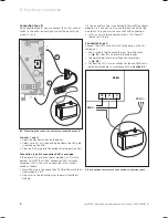
5.2
Connecting the safety cut-out switch, connection type A
Variants I. and II.
>
Open the electronics box on the boiler.
>
On the boiler PCB, remove the plug from the blue socket
which is labelled as either "Anl-Therm" (
I.
) or "Burner
off" (B.Off) (
II.
) (
1
).
>
Instead, plug the Pro-E plug on the connection cable of
the safety cut-out switch into the blue socket which is
labelled as either "Anl-Therm" (
I.
) or "Burner off" (B.Off)
(
II.
)(
2
).
2
1
BUS
RT
B. off
3
5.3
Connecting the safety cut-out switch, connection type A
Variant III.
>
Open the electronics box on the boiler.
>
Remove the cable bridge from the plug on the PCB of
the boiler (
1
).
>
Remove the Pro-E plug from the connection cable of the
safety cut-out switch (
2
).
>
Instead, connect the free cable ends of the connection
cable to the "Burner off" (B. off) terminal block (
3
).
Содержание ecoLEVEL
Страница 21: ......
Страница 22: ......
Страница 23: ......
Страница 24: ...0020029316_01 GBIE 102012 Subject to change Manufacturer Supplier ...


