Appendix
54
Installation and maintenance instructions auroCOMPACT 0020181589_04
Code
Meaning
Cause
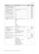
F.74
Water pressure sensor signal outside correct
range (too high)
Line to water pressure sensor has a short circuit to 5 V/24 V or internal
fault in the water pressure sensor
F.75
Fault: Insufficient throughput on pump start-up.
Pump defective, air in heating installation, too little water in unit, mass
flow sensor defective
F.77
Fault: Flue non-return flap/condensate pump
No response from flue non-return flap or condensate pump defective
F.81
Cylinder charging pump fault
Air in heating and hot water circuit, charging pump malfunction
F.82
Impressed current anode fault (if installed as an
accessory)
Connection of anode or PCB of impressed current anode defective
F.83
Fault: Flow and/or return temperature sensor
temperature change
When the burner starts, the temperature change registered at the flow
and/or return temperature sensor is non-existent or too small
–
Insufficient water in product
–
Flow or return temperature sensor not in correct position at pipe
F.84
Fault: Flow/return temperature sensor temperat-
ure difference implausible
Flow and return temperature sensors returning implausible values.
–
Flow and return temperature sensors have been inverted
–
Flow and return temperature sensors have not been correctly in-
stalled
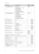
F.85
Fault: Flow and return temperature sensors
incorrectly installed
The flow and/or return temperature sensors have been installed on the
same pipe/incorrect pipe
F.86
Fault: Floor contact
Activate the overheating thermostat for the underfloor heating: Set the
heating target value
F.90
Fault: No communication between SMU and
BMU
Interruption between BMU and SMU, faulty product code
F.92
Coding resistance fault
The coding resistance on the PCB does not match the entered gas
group: Check the resistance, repeat the gas family check and enter the
correct gas group.
F.93
Gas group fault
Combustion quality outside the permitted range: Incorrect gas restrictor,
recirculation, incorrect gas group, internal pressure measuring point in
Venturi blocked (do not use lubricant on the O-ring in the Venturi).
Commu-
nication
fault
No communication with the PCB
Communication fault between display and PCB in the electronics box
F.1018
Solar pump control system fault
Pump control cable harness disconnected.
F.1020
Safety switch-off: Temperature limiter
Solar cylinder temperature too high
F.1021
Solar pump running dry
Lack of solar fluid in solar circuit.
F.1070
SMU configuration error
Incorrect coding resistance identified
F.1273
Solar pump electronics fault
Connection fault, fault in pump PCB
F.1276
Solar pump blocked
Solar pump defective
F.1278
Panel sensor fault
Sensor incorrectly connected or defective
F.1279
Fault in sensor on lower part of cylinder
Sensor incorrectly connected or defective
F.1355
Mass flow sensor fault
Flow sensor defective or not connected, power supply or PWM control
system of solar system not connected, solar valve (blue or red) closed,
air in solar circuit, pressure in solar circuit too low.


