Appendix
50
Installation and maintenance instructions auroCOMPACT 0020181589_04
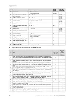
Code Parameter
Values or explanations
Default
setting
User-spe-
cific setting
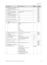
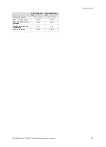
D.200 Solar function
0 = Function activated
1 = Function deactivated
0 = Function
activated
D.201 Temperature sensor on the lower
part of the cylinder
−
99 … 120
℃
Not ad-
justable
D.202 Collector temperature sensor
−
99 … 155
℃
Not ad-
justable
D.203 Solar pump speed
In %, adjustment range: 0 to 100
Not ad-
justable
D.205 Solar yield
In kWh
Not ad-
justable
D.206 Maximum cylinder temperature with
solar energy
20 … 80
℃
80 °C
D.207 Solar flow rate
0 … 15.15 l/min
Not ad-
justable
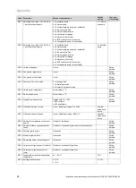
D.209 Operating hours of the solar pump
h
Not ad-
justable
D.210 Brine concentration
0 … 100 %
42
D.211 Reset the solar yield
0 = Solar yield not initialised
1 = Solar yield initialised
D.212 Delta T between the cylinder temper-
ature and solar panel in operation
7 … 20
℃
7
D.213 Delta T between the cylinder tem-
perature and solar panel when the
system is idle
2 … 5
℃
3
D.217 Collector surface area
In m
2
, between 1 and 10
2
C
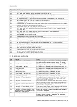
Inspection and maintenance work
–
Overview
No.
Work
Inspection
(annual)
Mainten-
ance
(at least
every
2 years)
1
Check the air/flue pipe for leak-tightness and to ensure that it is fastened correctly. Make sure
that it is not blocked or damaged and has been installed in accordance with the relevant Installa-
tion Manual.
X
X
2
Check the general condition of the unit. Remove dirt from the product and from the combustion
chamber.
X
X
3
Visually inspect the general condition of the heating block. In doing so, pay particular attention
to signs of corrosion, rust and other defects. If you notice any damage, carry out maintenance
work.
X
X
4
Check the gas connection pressure at maximum heat input. If the gas connection pressure is not
within the specified range, carry out maintenance work.
X
X
5
Check the CO
₂
content (the air ratio) of the product and, if necessary, adjust it. Keep a record of
this procedure.
X
X
6
Disconnect the product from the power mains. Check that the electrical plug connections and
other connections are seated correctly and correct these if necessary.
X
X
7
Close the gas isolator cock and the service valves.
X
8
Drain the product's heating circuit. Check the pre-charge pressure of the expansion vessel and
top up the vessel, if necessary (approx. 0.3 bar below the system filling pressure).
X
9
Allow the pressure in the hot water circuit to fall. Check the pre-charge pressure of the expan-
sion vessel in the shift-load cylinder (if installed). Correct the pressure, if necessary.
X
X
10
Check the extent to which the anode is corroded and replace it if necessary.
X
X
11
Remove the compact thermal module.
X
12
Check all seals in the combustion area, in particular the seal on the burner door. If you see any
damage, replace the seals.
X
13
Clean the heat exchanger.
X
14
Check that the burner is not damaged and, if required, replace it.
X
15
Check the condensate siphon in the product, clean and fill if necessary.
X
X


