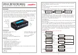
background image

9 Trouble Shooting

Table 9-1 FAQ

Please refer to the table below to deal with common faults

Phenomenon

Possible Cause

Solution

The indicator 

does not flash

The power cable of the battery pack is not  

properly connected.

Reconnect the power cable of the battery pack 

The power switch is off.

Turn on the power switch. 

The BMS is in a sleep state.

Charge the battery pack 

BMS is damaged.

Replace BMS.

Unable to 

discharge

The terminal of the battery pack is 

damaged.

Replace the battery pack wiring terminals. 

BMS communication failure.

Reconnect the communication line between the BMS 

and the battery pack. If the communication cable is  

damaged, replace the communication cable.

The power switch is off.

Turn on the power switch.

Unable to 

charge

The charger is malfunctioning.

Replace the charger.

The terminal of the battery pack is  

damaged.

Replace the battery pack wiring terminals. 

BMS communication failure.


Reconnect the communication line between the BMS 

and the battery pack. If the communication cable is 

damaged, replace the communication cable. 

The power switch is off.


Turn on the power switch.

Communication 

fail

The power switch is off.


Turn on the power switch.

The BMS is in a sleep status.

Charge the battery pack 

The communication cable is damage.

Replace the network cable. 

Inaccurate 

voltage display

The voltage sampling line is damaged.


Replace the voltage sampling cable.

BMS is damaged.

Replace BMS.

Low capacity

The battery pack has not been maintained  

for a long time.


Use an equalizer to maintain the battery pack. 

The single battery is damaged.

Replace the damaged single battery.

Inaccurate voltage sampling.


Replace the electrical sampling line or replace the BMS. 

Low cell 

voltage

The battery pack has not been maintained  

for a long time.

Use an equalizer to maintain the battery pack. 

The single battery is damaged.


Inaccurate voltage sampling.

Replace the damaged single battery.

Replace the electrical sampling line or replace the BMS. 


Содержание VT-48200B

Страница 1: ...OW 9B Thank you for selecting and buying V TAC Product V TAC will serve you the best Please read these instructions carefully keep this user manual handy for future reference If you have any another q...

Страница 2: ...owing signs may appear in this article and their meanings are as follows Sign Meaning Description Danger Indicates a hazard with a high level of risk that will cause death or serious injury if not avo...

Страница 3: ...directly damaged External short circuit If the battery pack is short circuited externally the battery will be directly damaged Series connection application The battery pack does not support the appli...

Страница 4: ...process of using which can save customers battery operation maintenance testing costs and reduce the frequency of on site replacement Long cycle life The battery pack life is 3 times long than the ord...

Страница 5: ...ction Extended function Extended SNMP V2 SNMP V3 LCD anti theft etc Figure 3 1 Normal Working Operation Diagram of The Battery pack 3 Overview 3 2 Application Scenario The battery pack is used to prov...

Страница 6: ...irect charging of the battery below 0 C When the minimum temperature of the battery is below 0 C the BMS will cut off the charging circuit and cannot be charged Low temperature Discharging The battery...

Страница 7: ...or the environment on the sea days 25 C 15 days 45 C The battery needs to be recharged in time after storage otherwise the battery may be damaged due to over discharge and the entire battery pack nee...

Страница 8: ...M Alarm light Address range 0 15 4 RJ 11 RJ 11 interface for firmware Used for debugging 5 RJ 45 CAN 2 RJ 45 interface for RS485 CAN communication Details shows in table 5 7 6 RESET Reset switch 8 9 D...

Страница 9: ...to identify the current capacity status of the battery The number of flashing indicators corresponds to different remaining capacity The specific meaning is shown in the following table Flash Mode ON...

Страница 10: ...OFF OFF OFF OFF Standby Normal Flash 1 OFF According to SOC Flash mode shown in Table 2 Charge Normal Flash 2 ON OFF OFF According to SOC According to SOC Error Abnormal OFF ON OFF Discharge Normal A...

Страница 11: ...Introduction The relationship between DIP address and BMS address as below DIP 1 DIP 2 DIP 3 DIP 4 BMS Address OFF OFF OFF OFF 0 ON OFF OFF OFF 1 OFF ON OFF OFF 2 ON ON OFF OFF 3 OFF OFF ON OFF 4 ON O...

Страница 12: ...Definition RJ 45 CAN Photo Pin Description 4 RS485_A 5 CAN_L 6 CAN_H 7 RS485_B 8 GND 1 2 3 NC Dry Contact No Alarm Definition Dry Contact 1 Dry Contact 2 Battery lock 940 module fault NTC disconnectio...

Страница 13: ...ith insulation tape for insulation treatment The following table describes the tools and meters that may be used before installation Manual forklift Electric forklift Electric screw driver Adjustable...

Страница 14: ...d please do not proceed to the next installation 6 Installation 6 2 Unpacking and Inspection Make sure to disconnect and isolate the battery from any electrical source and then turn on the MCB switch...

Страница 15: ...6 Installation Figure 6 2 Fix the Battery on the Cabinet or Rack Figure 6 3 Right Way to Place Battery 2 Put the battery into cabinet or rack As shown in Figure 6 2...

Страница 16: ...case of several battery parallel connection it is advisable to leave a space of at least 10mm between them NOTE Figure 6 4 Connect Ground Cable Pay attention to the polarity of the battery pack Connec...

Страница 17: ...unication cable to connect the battery packs in series through the RS485 communication port and connect the battery packs at the end to the user s RS485 communication port through the RS485 communicat...

Страница 18: ...re that the bus bars at the user end are in disconnected state Pay attention to the polarity of the battery pack ATTENTION 6 Installation Figure 6 7 Connect the 120 Resistor To ensure stable CAN commu...

Страница 19: ...connectors are fastened Check whether the battery pack s power cable terminal is snapped into place and covered with an insulating cover Check whether the long cables are bundled Check whether the com...

Страница 20: ...us If the RUN indicator of the battery is on and the ALARM indicator is off indicating that the battery is working normally 4 Please configure the actual number of batteries in parallel connection thr...

Страница 21: ...Select the actual number of batteries in parallel connection on the SYSTEM PACK SUM 4 Click the Write button to finish the setting 5 Restart the battery 2 3 4 Figure 7 2 Configuration Page Please refe...

Страница 22: ...ally If the displays normally then we can know the battery is well and the parameter settings are right 7 1 4 Check by UI software NOTE Follow the power on procedure to power on the battery pack stric...

Страница 23: ...voltage V 50 0 53 3 9 LLVD V 47 0 50 1 10 BLVD V 43 2 46 1 11 Temperature compensation for float charge mV C NA NA Temperature compensation for equalization charge mV C NA NA The content in the table...

Страница 24: ...orage with low battery may damage the battery All maintenance work must be carried out by professionals It is suitable for the transportation of vehicles ships and airplanes During transportation shad...

Страница 25: ...olution as per alarm information If the surface is dirty clea n the appearance of the battery pack with a cotton cloth The battery pack terminal is damaged replace the cable If the appearance is damag...

Страница 26: ...dation after long term storage please shorten shelf time as possible as you can Recharge charge before using to recover capacity loss of self discharge during storage and transport Storage battery sho...

Страница 27: ...nals BMS communication failure Reconnect the communication line between the BMS and the battery pack If the communication cable is damaged replace the communication cable The power switch is off Turn...

Страница 28: ...by continuous overload work outside the electrical parameters of the equipment is not covered by the warranty 4 Unauthorized testing of the equipment without the authorization of Vestwoods and author...

Страница 29: ...OC Battery Management System Depth Height Width Liquid Crystal Display LiFePO4 Metal Oxide Semiconductor Field Effect Transistor Negative Temperature Coefficient Personal Computer Printed Circuit Boar...

Отзывы: