


Page 62
11.
Adjust the Bass and Treble controls to provide the required low and high frequency
response.
12.
Adjust the remaining equalizer controls to put each RTA band within the limit lines. Avoid
extreme variation between adjacent equalizer values. The auditorium will generally sound
best applying the least equalization possible while remaining within the curve limit lines.
13.
Adjust the Equalizer Tab gain control for the desired auditorium SPL.
14.
Turn off the generator.
15.
Use the copy button to copy the equalization to each of the other channels as a starting
point.
16.
Go back to step 6 to equalize the next channel.
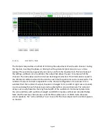
8.11.5
LFE EQUALIZATION PROCEDURE
The LFE channel uses a parametric equalizer instead of a graphic equalizer. In the below image,
the leftmost Gain control is the master LFE gain that applies to all LFE outputs. It corresponds to
the LFE gain control shown on the Outputs tab. Within each LFE box is another gain control that
applies to ONLY that LFE output. The box also contains the parametric filter controls (PEQ gain,
Q, and frequency) that applies to that particular LFE output.
The GUI determines the capabilities of the particular JSD-‐60 hardware and only shows the
appropriate number of LFE outputs.
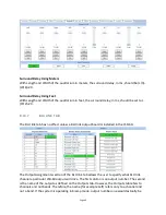
A suggested LFE adjustment procedure is below. Note that selecting the LFE channel in the
equalizer tab does NOT turn off pink noise on the previously selected channel. This is different
than the behavior on all other channels. This difference allows pink noise to drive the LFE and
center channels simultaneously so the transition frequency region can be viewed for possible
phase errors. When the LFE channel is selected on the equalizer tab, a warning box (shown in
the image below) will appear if pink noise is currently driving another channel. The procedure
below drives the LFE and center channels simultaneously.
1.
On the Equalizer tab, select the Center channel, Pink noise, and turn on the generator. Pink
noise should be visible on the RTA based on the equalization done in the previous section.
2.
Select the LFE channel. The warning box should appear indicating that the center channel is
also being driven. At this point, pink noise is driving both the center and LFE channels.
3.
Adjust the leftmost (master) gain control until the LFE level matches the mid-‐band level of
the center channel on the RTA display.
4.
Adjust the frequency control to the worst dip or peak in the LFE portion of the RTA display.
5.
Set the Q to 4 and adjust the PEQ gain as required to remove the peak or dip. The Q can be
increased to make the peak or notch narrower, or decreased to make it wider. The
frequency can be adjusted as required to center the peak or notch on the notch or peak
displayed on the RTA.
6.
If desired, a higher pass filter can be enabled under the filters tab adjusted to add a bit
more low frequency range. Try increasing the Q above the default 0.707, then adjust the
Содержание JSD-60
Страница 2: ... Page 2 ...
Страница 10: ... Page 10 3 1 DECLARATION OF CONFORMITY ...
Страница 96: ... Page 96 JSD 60L and JSD 60D rear view JSD 60LX and JSD 60DX rear view V150219 ...