


Version 160624
Page 43
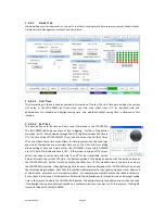
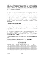
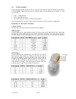
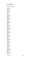
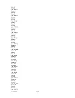
Rear Silk Label
(Optional)
Channel
Label
Full Range
Audio Channel
AES
Pair
Phoenix Optional
Output Pins (+, -, shield)
DB25M Monitor 2
Output
Pins (+, -, shield)
Lm/LCh (CH9)
Lsf
9
5
4, 5, 3
14, 15, 7
Rm/RCh(CH10)
Rsf
10
11, 12, 13
9, 22, 7
Lrs+ Lrs-
Lrs
11
6
16, 17, 18
16, 3, 7
Rrs+ Rrs-
Rrs
12
19, 20, 18
19, 6, 7
Cm+ Cm- (CH13)
Lsh
13
7
6, 7, 8
4, 18, 7
Ch+ Ch- (CH14)
Rsh
14
9, 10, 8
5, 17, 7
Lh+ Lh- (LFE2)
CEA
15
8
1, 2, 3
13, 12, 7
Rh+ Rh- (LFE3)
CEB
16
14, 15, 13
8, 20, 7
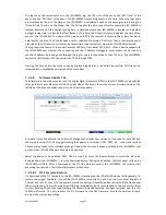
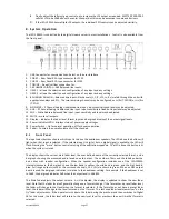
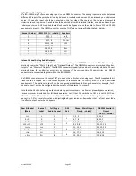
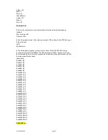
HI/VI-N Outputs
The JSD-100MA has balanced HI and VI-N outputs that can drive balanced or unbalanced loads. As with other
outputs, the use of twisted pair shielded cable is suggested whether the load is balanced or unbalanced. When
driving an unbalanced load, connect the “ – ” output of the JSD-100MA to low side of the unbalanced input at
the destination end of the cable to minimize ground loop noise. The source of audio to drive the HI and VI-N
outputs is configurable on a per-format basis. The HI audio output can be driven from AES inputs 7 or 15, or
from a main audio mix. The USL supplied ferrite block should be clipped on to the cables adjacent to the
connectors to comply with FCC and CE emission requirements.
Audio Channel HI/VI-N Phoenix Connector Pins (+, -, shield)
HI
1, 2, 3
VI-N
4, 5, 3
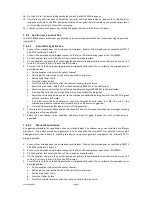
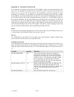
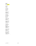
Parallel Automation Interface
Pins 1 - 10 of the DB25F automation connector are “control” pins that accept contact closure or open collector
pulses to ground to select formats. On a format change, the corresponding pin is also pulsed low allowing this
interface to drive other equipment. Pulsing pin 11 low toggles the mute state. Pins 14 through 24 are “status”
pins. One of the pins 14 through 23 is pulled low continuously by the JSD-100MA to indicate the selected
format. These pins could drive LEDs with a 470 ohm series resistor to provide a remote format indication. The
JSD-100MA pulls pin 24 low when the system is muted. Pins 1 through 11 are internally pulled up to +8.4V.
They each source 400uA when grounded. A pin needs to be pulled below 2.6V for 10ms or more for the JSD-
100MA to recognize it as low. On a format change, the JSD-100MA pulls the appropriate pin low for 500ms.
+5V at 100mA is available on pin 13 to drive external LEDs or relays. The individual control and status outputs
can sink up to 150mA with an open circuit voltage of +12VDC for inductive loads like relays or +24V for non-
inductive loads (indicator lamps, etc.). Pin 12 is the “automation return.” Use this as the low side of switches
and indicators instead of using chassis ground. It is ground through a 10 ohm resistor to limit ground loop
current. The USL supplied ferrite block should be clipped on to the cables adjacent to the connectors to
comply with FCC and CE emission requirements.
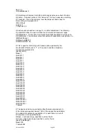
Pin
Description
1
Control 1. Pulse low to select format 1 (COAX1). Pulses low when format 1 selected.
2
Control 2. Pulse low to select format 2 (COAX2). Pulses low when format 2 selected.
3
Control 3. Pulse low to select format 3 (TOSLINK). Pulses low when format 3 selected.
4
Control 4. Pulse low to select format 4 (16 Channel Digital). Pulses low when format 4 selected.
5
Control 5. Pulse low to select format 5 (User 1). Pulses low when format 5 selected.
6
Control 6. Pulse low to select format 6 (User 2). Pulses low when format 6 selected.
7
Control 7. Pulse low to select format 7 (8 Channel Analog). Pulses low when format 7 selected.
8
Control 8. Pulse low to select format 8 (Non/Sync). Pulses low when format 8 selected.
9
Control 9. Pulse low to select format 9 (AUX). Pulses low when format 9 selected.
10
Control 10. Pulse low to select format 10 (MIC). Pulses low when format 10 selected.
11
Mute. Pulse low to toggle the mute state of the system.
12
Automation Return. Return control and status signals here.
13
+5V at 100mA to drive external indicators.
14
Status 1. Low when format 1 (COAX1) is selected.
15
Status 2. Low when format 2 (COAX2) is selected.


