


Version 160624
Page 16
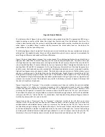
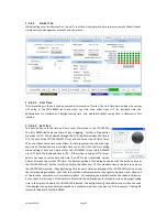
1.
Bypass Power Supply – 12VDC at 1.25A.
2.
Power entry Module – Accepts IEC-type line cord from 100-240VAC power source. Also contains a 500mA
Slo-Blo 5x20mm fuse.
3.
Sixteen Channel Analog Output Module
a.
Bypass crossover adjustments.
b.
Main outputs cover the first 8 output channels. The Phoenix connectors normally drive the power
amplifiers, and the DB25M connectors drive the booth monitor.
c.
Extra outputs cover the second 8 output channels.
d.
RS-485 - An RJ25 connector that provides an RS-485 interface for remote volume control and other
functions.
4.
Ethernet – Network communications with GUI, web browsers, automation, etc.
5.
RS-232 on a DE9F connector for communications with GUI or automation.
6.
Automation DB25F Connector – A bidirectional port for receiving and sending automation pulses between
the JSD-100MA and other system components. 12 Control lines, 11 Status lines and +5V are provided.
Standard pulse to ground system.
7.
SD Card - Stores a backup copy of unit configuration. Can also be used to transfer settings to another.
8.
AES connector (DB25F) – Channels 1-16
9.
AES connectors (Dual RJ45s) – parallel connections to the DB25F above.
10.
TOSLINK Port – Optical Fiber input for SPDIF (PCM).
11.
COAX 1, COAX 2 - RCA type connectors for SPDIF (PCM).
12.
Hearing Impaired/Visual Narration Outputs.
13.
AUX connectors – L and R analog inputs, 300mV sensitivity.
14.
Non Sync (N/S) connectors – L and R analog inputs.
15.
RTA microphone – 3.5mm stereo jack with +10V on the ring, designed for use with a powered electret
microphone.
16.
8 Channel Analog Input on DB25F – Balanced line inputs. Six channels are fixed (L, C, R, LFE, Ls, Rs) and
two can be set up as either Lc/Rc or Lrs/Rrs.
17.
Public Address Microphone – Dual connector with XLR and ¼” phone jack in the center.
6.4
Audio Input Connections
6.4.1
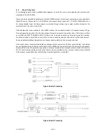
16 Channel AES Input
The JSD-100MA accepts 16 channel AES audio. This input is typically driven by the digital cinema server (DCS).
The JSD-100MA includes a DB25F connector using an industry standard
1
pin out and a pair of RJ-45 connectors
using the StudioHub
2
pin out. The first six channels are assigned speakers by industry convention. The
remaining channels are configured by default to provide a 15.1 channel sound field. The input sources for
HI/VN are user configurable. For convenience, all connector pin outs are listed in Appendix A.
6.4.2
8 Channel Analog Input
The JSD-100MA eight channel analog input is on a DB25F connector. The analog inputs are active balanced
(differential) inputs. They may be driven by balanced or unbalanced sources. When driven by an unbalanced
source, the negative input should be connected to the low side of the source at the source equipment to
1 The XSP-1000 DB25 AES input uses a de-facto industry standard pin out. The pin out was the subject of a draft SMPTE Engineering
Guideline in 2004. Though SMPTE never adopted the guideline, much of the industry adopted the pin out specified in this draft.
2 Please see the Studio Hub website: www.StudioHub.com


