


Version 160624
Page 12
5.1
Ls
C
L
R
Rs
7.1SDDS
Lc
Rc
7.1DS
Lrs
Rrs
LFE
C
L
R
LFE
C
L
R
LFE
Ls
Rs
Ls
Rs
4.4
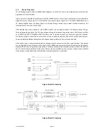
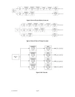
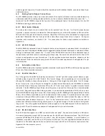
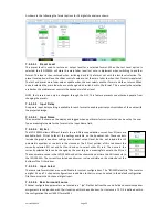
Sound Field Configurations
The standard sound field configurations (or speaker configurations) as defined by SMPTE are shown in the
diagram below. Note there are two defined 7.1 configurations. One (7.1DS) has rear surround speakers, while
the other (7.1SDDS) extends the side surround speakers to the rear wall and adds left center and right center
speakers. The JSD-100MA by default is configured as a 16.1 channel cinema processor not shown in the
illustration below.
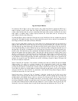
The JSD-100MA is configured for the particular speaker configuration in the auditorium. Each format is then
configured as to how the speakers in that auditorium are driven. For example, when an auditorium is
configured for 7.1DS, which includes rear surround speakers, and 5.1 content is played, the rear surround
speakers can be driven by the surround channels, or a mix of the surround channels.
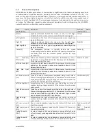
4.5
Processing Channels
The JSD-100MA has 16 “processing channels.” Each of these receives audio from a variety of sources. The
“processing channel” includes the main fader control, equalization, synchronization or input delay, surround
delay (on the surround channels), and, as an option, crossovers on the screen channels. Outputs on the rear
panel are identified by the channel usage (i.e., L for left). The table below describes the processing channels,
their inputs, and how their outputs are identified on the rear panel.
Input Channel
AES-EBU
Processing Channel
Channel
Label
Output Panel
Identifier
1
Left
L
L
2
Right
R
R
3
Center
C
C
4
Low Frequency Effects
LFE
LFE
5
Left Side Surround
Lss
Ls
6
Right Side Surround
Rss
Rs
7
Left Screen Height
LH
Lrs(Lc)
8
Right Screen Height
RH
Rrs(Rc)
9
Left Side Front Surround
Lsf
Lm/LCh (CH9)
*Note1
10
Right Side Front Surround
Rsf
Rm/RCh (CH10)
*Note 1
11
Left Rear Surround
Lrs
Lrs
*Note 1
12
Right Rear Surround
Rrs
Rrs
*note 1
13
Left Side Height
Lsh
Cm (CH13)
*Note 1
14
Right Side Height
Rsh
Ch (CH14)
*Note 1
15
Ceiling Channel A
CEA
Lh (LFE2)
*Note 1
16
Ceiling Channel B
CEB
Rh (LFE3)
*Note 1
Notes: 1. Signal located in the Optional Outputs connector.


