


Version 160624
Page 37
8.
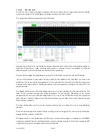
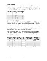
Finally, adjust the leftmost gain control up to increase the LFE output as required. SMPTE RP 200-2002
calls for LFE to be 10dB above the center channel, but this may be excessive in some auditoriums.
9.
If the JSD-100MA has multiple LFE outputs, the individual PEQ controls can be adjusted similarly.
8.
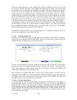
System Operation
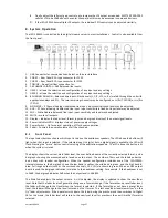
The JSD-100MA is controlled by the digital cinema server in most installations. Control is also available from
the front panel.
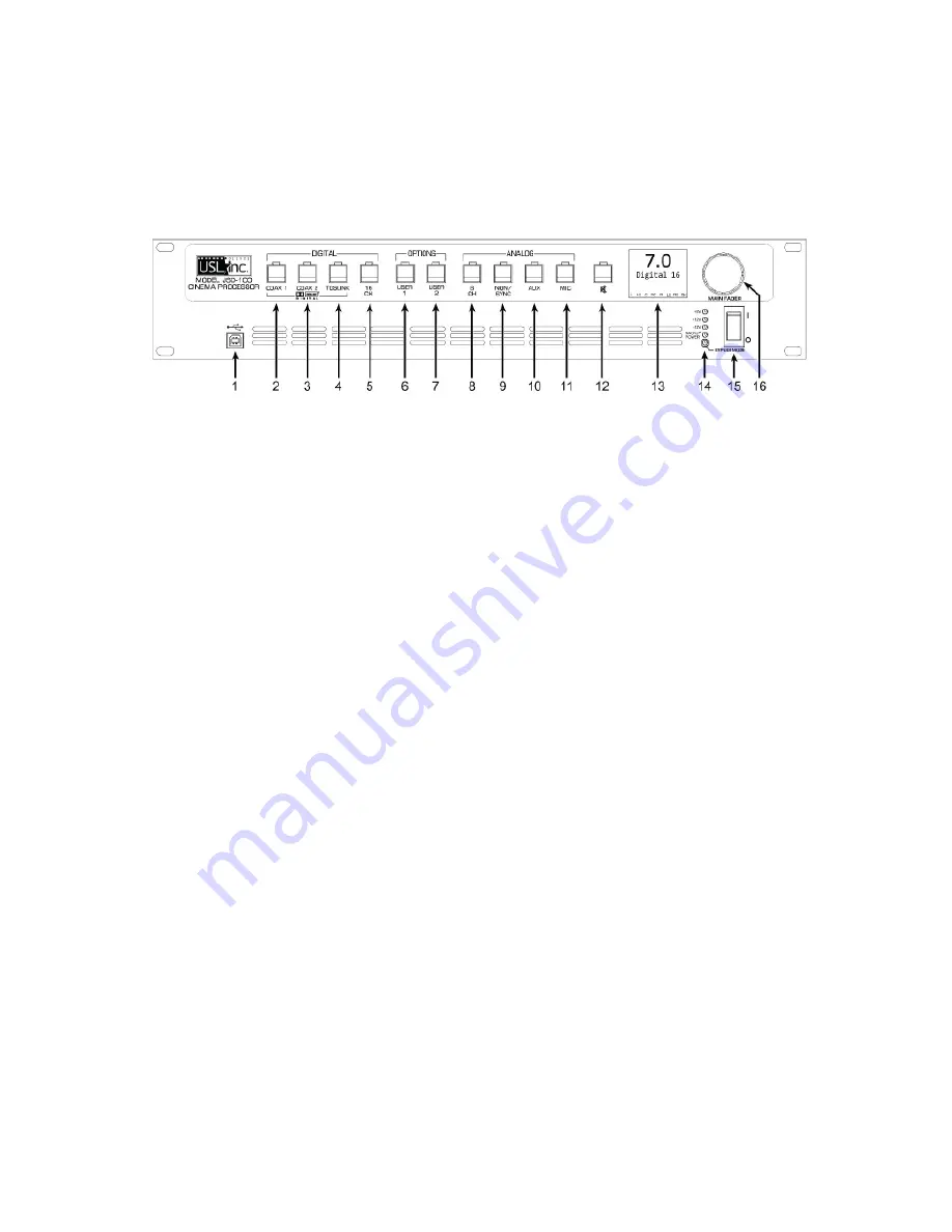
1.
USB Connector for communications. Select on the user interface
2.
COAX 1 – Rear Panel RCA type connector for PCM.
3.
COAX 2 – Rear Panel RCA type connector for PCM.
4.
TOSLINK – An optical fiber connection for.
5.
16 CHANNEL DIGITAL – AES Balanced line inputs.
6.
USER 1 – allows the selection and configuration of any input and any settings.
7.
USER 2 – allows the selection and configuration of any input and any settings.
8.
8 CHANNEL ANALOG – Balanced line inputs. Six channels (L, C, R, LFE, Ls, Rs) are fed through the unit with
appropriate delays and EQ. The two remaining channels may be configured as Lc/Rc (7.1SDDS) or Lrs/Rrs
(7.1DS).
9.
NON-SYNC – 2 Channel Analog Unbalanced Line Input. Input sensitivity and level may be adjusted.
10.
AUX – 2 Channel Analog Unbalanced Line Input. Input sensitivity is fixed but input level may be adjusted.
11.
MIC – Public Address Balanced line input. Input sensitivity and level may be adjusted.
12.
MUTE – mutes all outputs.
13.
Display – indicates the Fader level, format input and bar graph display of the output signal levels.
14.
Power Indicator LEDs – displays status of power supply voltages.
15.
Power Switch – On for normal operation, off for bypass operation.
16.
Fader – Controls the overall volume of all the channels.
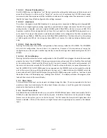
8.1
Front Panel
The input select buttons choose which input is to drive the auditorium speakers. The LED above the button will
light when that input is selected. If the selected input is digital, but no digital signal is available, the LED will
flash. Pressing the “mute” button controls muting of the auditorium speakers. The LED above the button is lit
when the system is muted.
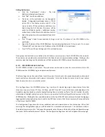
The display shows the current main fader level, the user defined name of the currently selected format, and a
bar graph showing the measured audio levels on each output. The number of bars and the labels under the
bars varies with speaker configuration. When the speaker configuration includes use of the JSD-100MA
internal crossovers, the bar graph shows the low band in yellow, the mid-band in green, and the high band in
blue. Full range outputs (such as the surround channels, HI, VI-N) are shown in green. When an AES output
board is used, the bargraph indication is relative to the headroom setting. For example, if the headroom is set
to 26dB, the bargraph indicates 0dB when the output level is -26dBFS.
The Main Fader adjusts the output volume. As it is adjusted, the display is updated to show the new fader
level. Note that the fader level will generally change on a format change. If the format has a preset fader level,
the fader will change to that level when the format is selected. If the format does not have a preset fader
level, the fader will change to the level last used on that format. The last used fader level memorizes “on the
fly” fader adjustments. If the operator turns down the fader during the preshow and then switches to Digital
16 for the movie, the fader level will return to the newly set level for preshows the next time that format is
selected.


