


Version 160624
Page 26
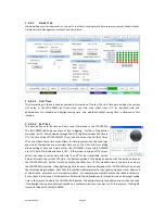
7.5.5.2.7 HI/VI-N Source
The HI output can be driven by a discrete input (such as AES channel 7) or an LCR mix. Most auditoriums are
wired to put HI on AES channel 7 since that is where the HI track is located in an Interop DCP. VI-N is typically
placed on AES 8. Some content, especially trailers and other preshow content, does not have a separate HI
track. The LCR mix will provide HI output whether the content has an HI track or not. The JSD-100MA has a
decoding feature to share the LFE channel with narration content by filtering the voice frequencies above
200Hz (LRC/LFE). This “frequency division multiplexing” splits the audio received on the LFE channel (typically
AES/EBU channel 4). Audio below 125Hz is sent to the LFE (SW) output. Audio above 200Hz is sent to the VI
output. When servers support this multiplexing, the JSD-100MA can deliver 15.1 audio along with HI/VI.
7.5.5.2.8 Decode Options
Two channel sources can be decoded out to several channels. These options are available on digital and
analog two channel formats, such as COAX1, COAX2, TOSLINK, NON/SYNC, and AUX.
Decode Option
Description
L_R
The two channel source drives just the left and right speakers.
L_C_R
The left and right channels of the source drive the left and right speakers. The center
speaker is driven with 0.707 times the sum of the left and right channels. The LFE channel
is driven with the center channel after passing through an 80Hz low pass filter.
Simple Matrix
The front speakers are driven with the same signals as L_C_R, described above. The
surround speakers are driven with 0.707 times the difference between left and right
(0.707(L-R)). The rear surrounds are driven with side surrounds (Lrs = Lss and Rrs = Rss).
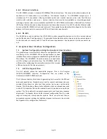
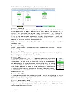
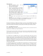
7.5.5.3
Equalizer Tab
The JSD-100MA equalizer allows the frequency
response of the JSD-100MA to be adjusted for
the acoustics of the room. The RTA screen
shows the measured sound pressure level
(SPL), the measured level in each 1/3 octave
spectrum band, and limit lines for the desired
equalization. By default, the limit lines
correspond to the SMPTE ST 202:2010 limits for
a 500 seat auditorium. Other limit sets can be
displayed (see Curve File, below). The equalizer
tab also allows access to the automatic
equalization feature of the JSD-100MA.
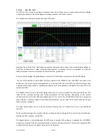
7.5.5.3.1 RTA Channel Select Buttons
Channel select buttons are along the top of the RTA window. These select which speaker the generator is
driving and which channel the equalizer controls are adjusting. If an external pink noise generator is to be used
with the internal RTA, enable the internal pink noise generator, then disable it. Enabling the internal pink noise
generator configures the internal RTA for proper operation.
7.5.5.3.2 RTA Settings
When the mouse cursor is over the display area of the RTA, another row of settings becomes visible (as shown
above). Use the Source button to select whether the “cal” (calibration) or “pa” (public address) microphone
input is being used to drive the RTA. The calibrate microphone input is on the 3.5mm TRS connector on the
rear panel. The PA microphone input is on the combination XLR ¼ inch TRS connector. Use the Zoom buttons
to enlarge or reduce the text within the RTA display area. Use the dB/step selector to adjust the vertical
resolution as required for viewing all bands on screen while providing the best vertical resolution. Make initial
adjustments with a fast decay time. The fast decay time provides a faster update, but a less stable display. As
you close in on the final adjustment of the equalizer, increase the decay time towards maximum to provide a
stable display and precise indication of the equalization. Use the Data Offset control to slide the RTA data up


