E N G L I S H
73
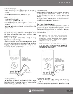
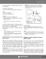
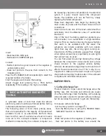
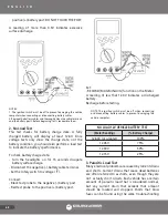
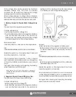
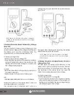
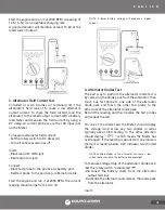
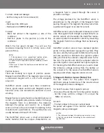
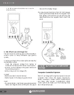
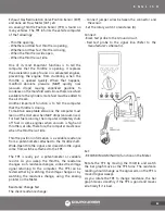
Connect:
- Black test probe direct to the positive (+) terminal on
the starter motor.
- Red test probe to the positive (+) battery post.
Set:
- RECORD (MAX-MIN-AVG) function on the meter.
Disable the ignition so the engine doesn’t start and
crank the engine for 4 ~5 seconds.
This connections has 4 connectors, 2 wires and 2
solenoid connections so a voltage drop of more than
800mV would indicate a poor circuit.
Test again after cleaning and inspecting the battery,
starter cables, solenoid and cable connections.
A defective starter solenoid cause an excessive voltage
drop.
Check the cables and connections before replacing
the solenoid.
NOTE: Repeat this test when the engine is thoroughly
warmed up. Heat expansion of metal may cause voltage
drop to increase.
Starter Motor Current Test
The battery tests and the voltage drop tests have
verified that there is adequate battery voltage at the
starter. Next, investigate how much current the starter
is drawing by using a DC clamp-on current probe.
Under normal operating conditions, with an outside
air temperature of 70°F, a good rule of thumb for
calculating cranking current is 1A per CID (Cubic Inch
Displacement) for 60A per liter ± about 25%.
Under No Load conditions, it is 1/2" A per CID ± about
10%. Check the manufacturer’s specifications for the
correct starter cranking current.
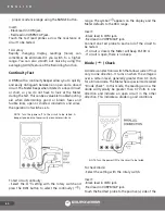
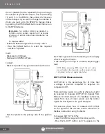
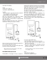
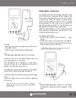
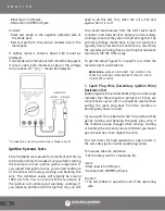
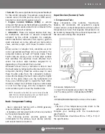
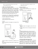
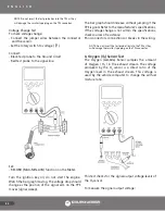
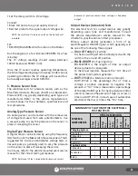
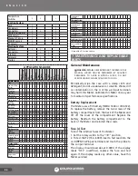
To measure start current:
- Set the rotary switch to the millivolts DC ( )
setting.
- Connect a DC clamp-on current probe to the Meter.
- Let this current probe clamp around the positive (+)
terminal cable of the starter motor.
NOTES: Make sure the arrow on the clamp is pointed in the
direction of the current flow in the cable.
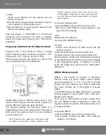
Set:
- RECORD (MAX-MIN-AVG) function on the Meter.
The Minimum reading will be the negative current
draw.
Содержание UD88
Страница 94: ...94 NOTAS NOTES ...
Страница 95: ...95 NOTAS NOTES ...

