E N G L I S H
85
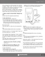
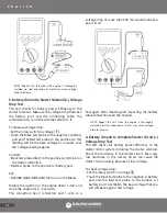
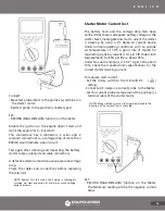
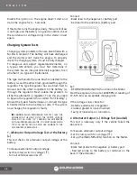
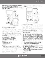
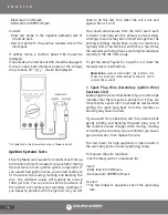
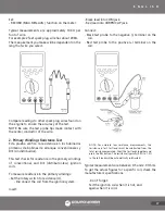
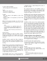
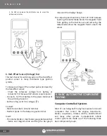
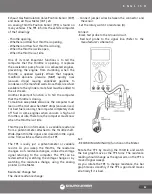
• Set the rotary switch to DC voltage.
Connect:
• Black test probe to a good quality Ground.
• Red test probe to the signal output voltage wire.
NOTE: Be careful not to burn yourself on the hot exhaust
manifold.
Set:
• RECORD (MAX-MIN-AVG) function on the Meter.
Run the engine at a fast idle (at 2000 RPM for a few
minutes).
The O² voltage readings should sweep between
100mV (lean) and 900mV (rich).
Once the O² sensor reaches operating temperature,
the DC voltage reading begin to sweep. Under various
operating conditions the O² voltage will rise and fall,
but usually averages around 0.45V DC.
5. Pressure Sensor Tests
The electrical tests for pressure sensors such as the
Manifold Absolute Pressure (MAP) and Barometric
Pressure (BP) vary greatly depending upon type and
manufacturer. Refer to the vehicle manufacturer’s
service manual for the schematics, specifications and
test procedures.
Analog-Type Pressure Sensor
An analog sensor can be tested with the same series
of voltage tests used for 3-wire potentiometers. Use
a vacuum pump to vary the pressure on the sensor in
place of sweeping the sensor.
Digital-Type Pressure Sensor
A digital sensor can be tested by using the frequency
(Hz) function of the Meter with the same series of tests
suggested for 3-wire potentiometer voltage tests. A
Vacuum pump is generally used to vary the pressure
on the sensor in place of sweeping the sensor.
In all cases, refer to the vehicle manufacturer’s service
manual for the correct testing procedures.
NOTE: Resistance (Ω) test is impossible for pressure sensors
because all pressure sensors have voltage or frequency
output.
Output Devices (Actuators) Tests
The electrical tests for output devices vary greatly
depending upon type and manufacturer. Consult
the vehicle manufacturer’s service manual for the
schematics, specifications and test procedures.
Primary output devices generates a form of an
electromagnetic ON/OFF signal, which generally will
be one of the following three signals:
— On or Off only
(Ex. Switch)
:
To check a switch perform continuity tests with the
switch in the on and off position.
— PULSE-WIDTH
(Ex. Fuel injector)
:
PULSE-WIDTH is the length of time an output
device (actuator) is energized.
To check fuel injectors, measure the "On" time of
the pulses fuel injectors generate.
— DUTY-CYCLE
(Ex. Mixture control solenoid)
:
DUTY-CYCLE is the percentage (%) of time a
voltage is positive compared to negative. The
amount of "On" time is measured as a percentage
of the total On/Off cycle. To check a mixture control
solenoid, measure the percent of high (+) or low (-)
time in a DUTY-CYCLE. In most cases of automotive
electronics the low (-) time is the "On" time.
SUMMARY OF AUTOMOTIVE ELECTRICAL
SYSTEM TESTS
SYSTEM &
COMPONENTS
TIPOS DE MEDICIÓN
Voltage
Pr
esence
& Level
Voltage
Dr
op
Curr
ent
(Amps)
Resistance
(Ohms)
Fr
equency
(Hz)
Charging System
Alternators
•
•
•
Connectors
•
•
•
Diodes
•
•
Regulators
•
•
Cooling System
Connectors
•
•
•
Fan Motors
•
•
•
Relays
•
•
•
Содержание UD88
Страница 94: ...94 NOTAS NOTES ...
Страница 95: ...95 NOTAS NOTES ...

