17
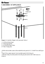
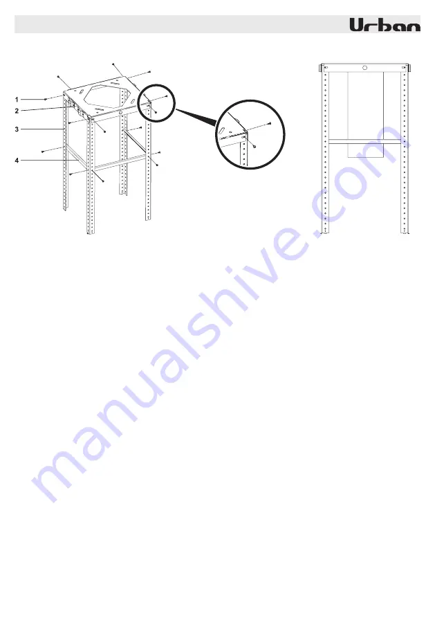
Figure 4:
Installation Diagram and Components Section
2
1.
3.5 x 9.5 R Phillips Cylinder Head Screw
2.
Ceiling Hanging Plate
3.
Product Hanging Bar
4.
Hanging Bars Balancing Component
•
Install product hanging bars (3) to ceiling hanging plate (2) with 8 pcs. 3.5 x 9.5 rysb screw (1)
(Figure 4)
•
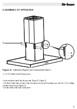
Install product hanging bars to balance hanging bar balancing components (4) with 6 pcs. 3.5 x
9.5 rysb screw (1).
•
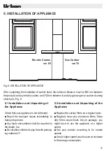
Make the air outlet connection of the product (Figure 4)
Figure 4a
8 ASSEMBLY OF APPLIANCE
Содержание I212-L ISLA 90 INOX
Страница 1: ...1 Lea el manual del usuario con cuidado I212 L ISLA 90 INOX ...
Страница 2: ...2 ...
Страница 28: ...1 Please Read The User Manual Carefully I212 L ISLA 90 INOX ...
Страница 29: ...2 ...
Страница 31: ...4 Fig 1 TECHNICAL DRAWING I212 L ISLA 90 INOX 4206 40 475 475 270 280 600 898 20 Min 650 Max 920 ...
Страница 55: ...1 Veuillez lire attentivement le manuel d utilisation I212 L ISLA 90 INOX ...
Страница 56: ...2 ...

