16
8 ASSEMBLY OF APPLIANCE
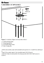
1.
4x Ø10mm Plastic Dowel
2.
Ceiling Hanging Plate
3.
4x 5.5x60 Wall Mount Screw
4.
Product Hanging Bar
Figure 3 :
Installation Diagram and Components Section 1
• Drill the surface where product will be installed from the points A, B, C, D with Ø10 mm drill (Figure
3).
•
Insert Ø10 mm plastic dowels (1) into the drilled points A,B,C,D (Figure 3).
•
Install the Ceiling Connection plate to the ceiling at points A,B,C,D with 5.5x60 screws (3).
(Figure 3).
Содержание I212-L ISLA 90 INOX
Страница 1: ...1 Lea el manual del usuario con cuidado I212 L ISLA 90 INOX ...
Страница 2: ...2 ...
Страница 28: ...1 Please Read The User Manual Carefully I212 L ISLA 90 INOX ...
Страница 29: ...2 ...
Страница 31: ...4 Fig 1 TECHNICAL DRAWING I212 L ISLA 90 INOX 4206 40 475 475 270 280 600 898 20 Min 650 Max 920 ...
Страница 55: ...1 Veuillez lire attentivement le manuel d utilisation I212 L ISLA 90 INOX ...
Страница 56: ...2 ...


