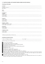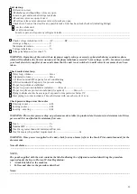
29
Unit start-up
Oil level is correct
All discharge and liquid line valves are open
Locate, repair and mark all refrigerant leaks
All suction valves are open, if used
All oil line valves and economizer valves (if used) are open
Checks have been carried out for any possible leaks. Unit has been leak checked (including fittings)
- on the whole unit
- at all connections
Locate, repair, and report any refrigerant leaks
......................................................................................................................
......................................................................................................................................................................................................
......................................................................................................................................................................................................
Check voltage imbalance: AB
............ AC ................. BC..................
Average voltage = .............................. V
Maximum deviation = ....................... V
Voltage imbalance = .......................... %
Voltage imbalance is less than 2%
WARNING: Operation of the unit with an improper supply voltage or excessive phase imbalance constitutes abuse
which will invalidate the Carrier warranty. If the phase imbalance exceeds 2% for voltage, or 10% for current, contact
your local electricity supplier at once and ensure that the unit is not switched on until corrective measures have been
taken.
Check cooler water loop
Water loop volume = .......................... litres
Calculated volume = .......................... litres
3.25 litres/nominal kW capacity for air conditioning
6.5 litres/nominal kW capacity for process cooling
Proper loop volume established
Proper loop corrosion inhibitor included .........litres of ...........................
Proper loop freeze protection included (if required) ................ litres of ..............................
Piping includes electric heater tape, if exposed to temperatures below 0°C
Inlet piping to cooler includes a 20 mesh strainer with a mesh size of 1.2 mm
Check pressure drop across the cooler
Entering cooler = ................................ kPa
Leaving cooler =
................................. kPa
Leaving - entering =
........................... kPa
WARNING: Plot cooler pressure drop on performance data table (in product data literature) to determine total litres
per second (l/s) and find unit’s minimum flow rate.
Total = .................................................. l/s
Nominal kW = .................................... l/s
Total l/s is greater than unit’s minimum flow rate
Total l/s meets job specified requirement of
......................................... l/s
WARNING: Once power is supplied to the unit, check for any alarms (refer to the Touch Pilot control manual for the
alarm menu).
Note all alarms:
.................................................................................................................................................................
...........................................................................................................................................................................................
NOTE:
The pouch supplied with the unit contains the label indicating the refrigerant used and describing the procedure
required under the Kyoto Protocol F-Gas Regulation:
•
Attach this label to the machine.
•
Follow and observe the procedure described.
Notes:
...........................................................................................................................................................................................


