United Technologies Carrier Touchpilot 30XW-V Скачать руководство пользователя страница 25

25

• 

Clean the water filter (see chapter 7 “Water connec-

tions”).

• 

Check the unit operating parameters and compare 

them with previous values.

• 

Keep and maintain a maintenance sheet, attached to 
each HVAC unit.

All these operations require strict observation of adequate 

safety measures: individual protection garments, compliance 
with all industry regulations, compliance with applicable 

local regulations and using common sense. 

11.3 - Level 3 (or higher) maintenance

See note below.

The maintenance at this level requires specific skills/
approval/tools and know-how and only the manufacturer, 

his representative or authorised agent are permitted to 
carry out these operations. These maintenance operations 

concern for example:
• 

A major component replacement (compressor, 

evapo-rator)

• 

Any intervention on the refrigerant circuit (handling 

refrigerant)

• 

Changing of parameters set at the factory (application 

change)

• 

Removal or dismantling of the HVAC unit

• 

Any intervention due to a missed established mainte-

nance operation

• 

Any intervention covered by the warranty.

NOTE: Any deviation or non-observation of these mainte-
nance criteria will render the guarantee conditions for the 
HVAC unit nul and void, and the manufacturer, Carrier 
France, will no longer be held responsible.

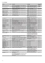
11.4 - Tightening of the electrical connections

11.4.1 - Tightening torques for the main electrical connections

Screw type

Designation

in the unit

Torque

value, N·m

Customer connection

Screw-nut M12 at phase decks

L1/L2/L3

50

Nut on earth terminal

PE

81

Downstream power connections in the control box

Screw M10 at downstream main disconnect deck (QS10)* L1/L2/L3

50

Earth terminal M10

50

Power connections in the variator

GS-

M10 nut on the phase pin

19-40

M10 nut on the earth pin

19-40

Compressor phase connection terminals

M12

1/2/3/4/5/6 on EC- 23

M16

1/2/3/4/5/6 on EC- 30

Compressor earth connection

Gnd on EC-

25

Control disconnect connections

Upstream and downstream screws at terminals

QF

2

ATTENTION: The tightening of the connections at the 

compressor terminals requires special precautions. Please 

refer to the chapter below.

11 - STANDARD MAINTENANCE

Air conditioning equipment must be maintained by profes-

sional technicians, whilst routine checks can be carried out 

locally by specialised technicians. See the standard  
EN 378-4.

Simple preventive maintenance will allow you to get the 

best performance from your HVAC unit:
• 

improved cooling performance

• 

reduced power consumption

• 

prevention of accidental component failure

• 

prevention of major time-consuming and costly 

inter-ventions

• 

protection of the environment

There are five maintenance levels for HVAC units, as defined 
by the AFNOR X60-010 standard.

11.1 - Level 1 maintenance

See note below. 

Simple procedure can be carried out by the user:
• 

Visual inspection for oil traces (sign of a refrigerant 

leak)

• 

Air heat exchanger (condenser) cleaning - see chapter 

“Condenser coil - level 1”

• 

Check for removed protection devices, and badly 

closed doors/covers

• 

Check the unit alarm report when the unit does not 

work (see report in the Touch Pilot control manual).

 
General visual inspection for any signs of deterioration.
 

11.2 - Level 2 maintenance

See note opposite.

This level requires specific know-how in the electrical, 
hydronic and mechanical fields. It is possible that these 
skills are avail-able locally: existence of a maintenance 
service, industrial site, specialised subcontractor.

In these cases, the following maintenance operations are 

recommended.

Carry out all level 1 operations, then:  
• 

At least once a year tighten the power circuit electrical 

connections (see tightening torques table).

• 

Check and re-tighten all control/command connections, 

if required (see tightening torques table).

• 

Check the differential switches for correct operation 

every 6 months.

• 

Remove the dust and clean the interior of the control 
boxes, if required. Check the filter condition (if used).

• 

Check the presence and the condition of the electrical 

protection devices.

• 

Replace the fuses every 3 years or every 15000 hours 

(age-hardening).

• 

Replace the control box cooling fans (if used) every 
five years.

• 

Check the water connections.

• 

Purge the water circuit (see chapter 7 “Water connec-

tions”).

Содержание Carrier Touchpilot 30XW-V

Страница 1: ...MAINTENANCE INSTRUCTIONS Variable Speed Water Cooled Liquid Chillers Variable Speed Water to Water Heat Pumps 30XW V 30XWHV Nominal cooling capacity 587 1741 kW Nominal heating capacity 648 1932 kW 5...

Страница 2: ...wiring 16 5 7 24 and 230 V power reserve for the user 16 6 APPLICATION DATA 16 6 1 Operating limits 16 6 2 Condenser side installation recommendation 16 6 3 Minimum chilled water flow 17 6 4 Maximum c...

Страница 3: ...lve 22 9 6 Pressure vessels 22 9 7 High pressure safety switch 23 9 8 Electronic expansion valve EXV 23 9 9 Moisture indicator 23 9 10 Filter drier 23 9 11 Sensors 23 9 12 Frequency variator 23 10 OPT...

Страница 4: ...the right place and direction on the unit The units can also be lifted with slings using only the designated lifting points marked on the unit Use slings or lifting beams with the correct capacity an...

Страница 5: ...and may cause heart irregularities unconsciousness or death Vapour is heavier than air and reduces the amount of oxygen available for breathing These products cause eye and skin irritation Decomposit...

Страница 6: ...witch it is necessary to recover the refrigerant charge these pressure switches are not installed on automatic valves Schraeder type If any maintenance operations are carried out on the unit lock the...

Страница 7: ...These regulations permitting condi tioning and recovery of halogenated hydrocarbons under optimum quality conditions for the products and optimum safety conditions for people property and the environ...

Страница 8: ...t to repair or recondition any safety devices when corrosion or build up of foreign material rust dirt scale etc is found within the valve body or mechanism If necessary replace the device Do not inst...

Страница 9: ...on an even surface maximum tolerance is 5 mm in both axes there is adequate space above the unit for air flow and to ensure access to the components the number of support points is adequate and that...

Страница 10: ...ng an installation consult the certified dimensional drawings supplied with the unit or available on request For the positioning of the fixing points weight distribution and centre of gravity coordina...

Страница 11: ...re of gravity coordinates refer to the dimensional drawings Condenser Evaporator Dimensions in mm A B C D E F 30XW V 30XWHV 1150 1997 1514 1164 4730 219 1 219 1 1280 1997 1514 1164 4730 219 1 219 1 14...

Страница 12: ...tonnes 186 186 257 250 172 172 172 164 157 Capacity control Touch Pilot inverter driven compressor electronic expansion valve EXV Minimum capacity 20 20 20 20 10 10 10 10 10 Evaporator Multi pipe floo...

Страница 13: ...380 421 Circuit B A 270 330 330 380 421 With option 81 A 540 660 710 760 842 Maximum power input with option 150B Circuit A kW 141 173 199 221 141 173 199 199 221 Circuit B kW 141 173 173 199 221 Wit...

Страница 14: ...with the unit 5 The factory installed disconnect switch es circuit breaker s is are of a type suitable for power interruption in accordance with EN 60947 3 corresponds to IEC 60947 3 6 The units are d...

Страница 15: ...l electricity supplier at once and ensure that the unit is not switched on until corrective measures have been taken 5 2 Voltage phase imbalance 100 x max deviation from average voltage Average voltag...

Страница 16: ...ort Evaporator pump control signal Condenser pump control signal This does not control condenser pump operation for this function add option 156 and flow switch Heating cooling change over Available a...

Страница 17: ...ondenser water flow rates are shown in the table in chapter 6 7 Evaporator and condenser water flow rates If the system flow is higher than the maximum unit flow rate select the option with one pass l...

Страница 18: ...ecessary to add a buffer water tank to the circuit in order to achieve the required volume The tank must itself be internally baffled in order to ensure proper mixing of the liquid water or brine Refe...

Страница 19: ...fewest elbows and horizontal pipe runs at different levels Below the main points to be checked for the connection Follow the water inlet and outlet connection direction shown on the unit Install manu...

Страница 20: ...es destabilisation of copper hydroxides and enlargement of particles Electric conductivity 10 600 S cm pH Ideal case pH neutral at 20 25 C 7 pH 8 7 2 Water connections The water connections are Victau...

Страница 21: ...slave units Water inlet Water outlet Water pumps for each unit included as standard for units with hydronic module Additional sensors for leaving water control to be connected to channel 1 of the slav...

Страница 22: ...signed for prolonged storage of 15 years under nitrogen charge with a temperature difference of 20 K per day 452000 cycles start ups with a maximum difference of 6 K between two neighbouring points in...

Страница 23: ...re switches with manual reset called PZH former DBK are backed up by high pressure switches that require resetting with a tool The high pressure switches that require resetting with a tool are called...

Страница 24: ...s the unit by communication bus to a building management system 580 1710 LON gateway 148D Two directional communication board complying with Lon Talk protocol Connects the unit by communication bus to...

Страница 25: ...of the connections at the compressor terminals requires special precautions Please refer to the chapter below 11 STANDARD MAINTENANCE Air conditioning equipment must be maintained by profes sional tec...

Страница 26: ...is included with the compressor This low pressure switch should be temporarily installed as a hard safety on the high pressure part of the compressor The purpose of this switch is to protect the compr...

Страница 27: ...e the fan if a replace fan alert warning is displayed in the alarm list For any other alarm or problem at the frequency variator contact the Carrier service department The frequency variators in the 3...

Страница 28: ...properly Unit ground wire has been connected Electrical circuit protection has been sized and installed properly All terminals are tight All chilled water valves are open All chilled water piping is...

Страница 29: ...nominal kW capacity for air conditioning 6 5 litres nominal kW capacity for process cooling Proper loop volume established Proper loop corrosion inhibitor included litres of Proper loop freeze protec...

Страница 30: ...30...

Страница 31: ...31...

Страница 32: ...es order No 13474 76 05 2013 Manufacturer Carrier SCS Montluel France Manufacturer reserves the right to change any product specifications without notice Printed in the European Union www eurovent cer...

Отзывы: